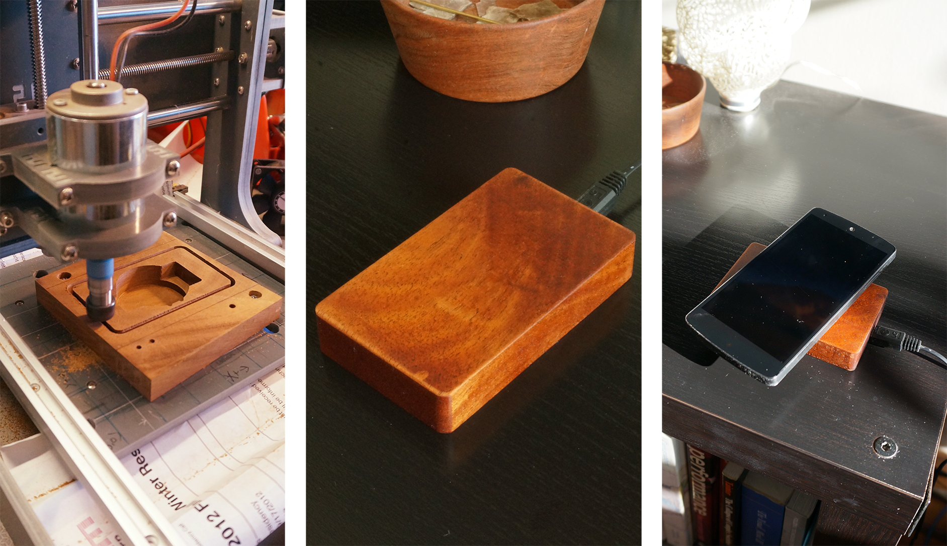
PhoneChargerTriptych
I’m surprised by how much I ended up liking my inductive charger for my phone. It sounds like such a trivial change, but not having to plug and unplug my phone every time I get to work, or go to bed, is delightfully convenient. Plus I don’t have to worry about wearing out my mini-USB connector by using it four times a day!

I made these little Qi chargers in a few hours using basic tools and a mini CNC mill. This project is an ideal place to hone your skills if you’re just starting out with your CNC mill, or if you’re looking to try your first electronics-and-wood milling job.

This project gets even easier the second and third times you try it, and these chargers make great gifts for the people in your life who have Qi-compatible phones — they’re beautiful, unusual, and useful. Once you’ve modeled the Qi charging board in your CAM of choice, it’s easy to riff on the other factors: have fun experimenting with different woods, different shapes, making the charging LEDs visible, and so on. And if you make a really cool one, I’d love to see a picture of it — let me know in the comments below.

What will the next generation of Make: look like? We’re inviting you to shape the future by investing in Make:. By becoming an investor, you help decide what’s next. The future of Make: is in your hands. Learn More.

Project Steps

1. MARSHALL YOUR MATERIALS

I sourced my wood from Rockler. They sell a 25lb assortment of hardwoods that are ideally sized for my CNC projects, and one box lasts me for quite awhile.

The woods I chose for my chargers are American walnut (a dependable, dark, and pretty hardwood) and mahogany. This was my first time working with mahogany, and I was delighted by the finish it takes with just a simple coat of mineral oil — it gets really luminous, almost-holographic grain detail. Mahogany also milled a little easier than walnut; I think this is because of the closer grain, but I’m not sure.

2. MEASURE AND PREPARE THE CHARGER

Sketch out on paper what dimensions you’d like your charger to have. I like mine to just about disappear under my Nexus 4, so I traced my phone on a piece of paper and measured out a rectangle roughly that size. You can change this in the CAM program later; this is just to get an idea of what you would like.

Now measure your Qi coil and PCB to make sure they will fit. Make sure you measure the heights of the coil and the board accurately! You can always make the pocket a little too deep, but it stinks if you make it too shallow — the circuit board will stand proud of the base, making it wobbly. The thicker the wood you’re using, the less clearance problems you’ll have later on.

a - the coil and board

I find it’s easiest to make a sketch of the coil and the board on a scratch sheet of paper and label out all the dimensions there — you can, of course, go all out and make a detailed model in SketchUp or other CAD software, but I like having a physical piece of paper around when I’m designing the tool path in my CAM software. Here’s what my sketch looks like.

b - traced out onto sketch pad

c - tracing annotated with dimensions

3. FIXTURE THE WORKPIECE

Next, and figure out the most convenient way to hold your rough blank to the mill’s machining surface. I use bolts that fit my spoilboard’s T-slots rather than hold-down clamps, because it’s less stressful to plan the toolpath if there are just screw-heads to avoid.

I tend to use 2 bolts placed at opposite corners of the piece and more than 2 tool-diameters away from the edges of the finished piece — for a ⅛” endmill this means I try to give myself at least ¼” of clearance on each side. If space is tight you can have less clearance, just be careful! I made a template to make it easier to remember where my mill’s T-slots run, and because I keep losing the template, I also used a Sharpie to write the T-slot spacing right on the spoilboard.

b - mark where to drill

You’ll notice I have extra holes in the piece I’m milling — I put the fixturing holes in the wrong place the first time. No worries, this happens to everyone, even people who write how-to articles.

Before you drill the holes for your holding bolts, scribe onto the rough piece itself where the boundaries of the finished piece should be. This is your last chance to easily change your design, so measure twice and drill once!

If you want to have the nicest possible surfaces on your finished piece, it’s worth taking the time to countersink the bolt-heads — that is, drill a hole all the way through the blank in a diameter that lets the bolt shank pass through, and then drill a hole in a larger diameter that will allow the bolt’s head to sit about 1mm below the wood’s surface. This greatly simplifies the first milling operation, which is flattening the whole surface of the piece.

4. ENTER STOCK DIMENSIONS IN CAM

Before you get to milling, now is the time to carefully measure your stock and tell your CAM program those dimensions. Measure the depth at all four corners of your piece; thickness of rough stock can vary a lot between edges, and your milling will go more predictably if you use the largest depth you measure: this way, you are never milling away more wood than you think you are, and this will be easier on your mill and your nerves.

c - entering the stock dimensions into CAD

When you think you are ready to cut, ensure that your piece is where the CAM software thinks your piece is. To do this, I just jog the Z-axis well above any pieces on the mill’s bed and then manually jog to the coordinates that the CAM thinks are the extrema of my piece. If the endmill goes where I expect, I am ready to cut.

z - rough idea of where we are milling

5. FACE THE TOP AND BOTTOM SURFACES

The first actual milling operation is facing the surface — this is where you take a tiny layer of wood off of the whole top of the piece, even the parts that won’t be part of your finished object. The goal here is to make sure that the surface we’re milling onto is perfectly flat relative to the mill. This is also a good time to make sure a bunch of parameters are set well – for example, that your piece is mounted sturdily, that your mill coordinates are well-reconciled with your piece’s outline, that your feedrate is reasonable, and so on.

I usually take 0.25mm off of the top surface when facing; you can take more if you like. Remember that after facing, your piece’s surface is now uniformly 0.25mm below where it used to be! Sometimes, the surface will be so rough that the –0.25mm cut does not touch some parts of the surface, leaving them unmilled. Since the goal here is to make the surface uniform, you should do the facing operation again, taking off another 0.25mm each time until your whole surface is milled.

a - begin facingb - finished facing the first side

For this piece, I’m also adding a profile operation — an outline cut — that simply cuts the end of the piece off. You don’t have to do this, but I wanted to make the rough piece easier to handle and orient. Because mahogany is harder than some other woods I’ve worked with, I also wanted to test the speeds I had set for the plunge rate (how fast the endmill moves straight down into the wood) and depth of cut (I chose a very conservative 0.25mm, I’m sure I could have done more).

I always flip the piece over and face the other side as soon as I’m done with the first facing operation, without worrying about registering the workpiece precisely.

c - begin facing the second side

6. MILL THE COIL POCKET

I calculated the center of the piece and put a circle there very slightly larger than the measured diameter of the coil. I also added two little circles so the coil’s wires wouldn’t be pinched as they passed back to the charging board — to place those, I put them each 5mm off of the X center axis, and just eyeballed their Y position so they were overlapping the circle’s circumference.

b - screenshot of feedrate-test, this is smartc - screenshot of coil-wireways-pocket

Now we want a pocket operation — this is where the machine removes the material inside a shape (in this case, the circle we’ll be putting our coil into).

To figure out the appropriate feedrate (I wanted to take deeper cuts than the 0.25mm cuts I used while facing, otherwise this would take forever), I made a “test cut” down to 1mm, taking 0.4mm cuts this time at 650mm/min. This is so I wouldn’t have to E-stop (emergency stop) the whole machine, potentially losing my tool’s location, if it turned out I had been cutting too aggressively. As it turned out, 0.4mm was still fairly conservative at 650mm/min and ~8k RPM, so I made another test cut, this time from –1mm to –2mm, to try out a 0.75mm cut. At this speed, I was hearing just a bit of chatter and vibration, so I decided to do the main pocketing with a 0.7mm depth of cut.

e - closeup of coil pocketing

7. MILL THE BOARD POCKET

For the circuit board, we just need make sure there’s enough clearance that the board doesn’t sit proud of the bottom of the piece, making it wobbly. Because I had a lot of room (this piece of wood is taller than most chargers I’ve been making), I set the pocket at –12mm.

In the CAM software, I could have just described a rectangle and cut that shape out, but you might see a couple of ways in which that is inefficient — for one, we would be cutting air, not wood, over the coil pocket, when we could just be skipping over it. To make sure my pocketing took as little time as possible, I selected the coil shape and the board shape in my CAM software and used the Break at Intersections function, which turned the circle and rectangle shapes into separate polylines. From there, I selected the polylines that each comprised the actual material I’d need to remove and used the software’s Join function to make them closed shapes. (I’m pretty sure I could simply have selected the non-joined polylines and then sent them to the Pocket operation, but I think it’s good practice to join shapes when appropriate — this makes it unambiguous later on, if you want to remake the piece, and also might surface any differences in understanding between you and the software).

b - screenshot of two poly-regions after intersection with coil-circle

I kept the same settings when pocketing the board: 0.7mm depth of cut, 650mm/min, 0.1mm final depth pass. A smaller final depth pass leaves a better finish, because the tool isn’t working against forces as great as usual. (For this piece the cuts won’t even be visible because they’re on the inside and will be covered by the board, but I have a habit of doing a careful final pass, so I left this in.)

Initially I thought I would select both polyline regions and then send them to the Pocket operation — do you see why I decided not to do this? The reason is that when you tell the CAM to do pockets on multiple areas of the workpiece, it generates Gcode whose cut order is “layer first,” meaning that it will do all cuts at a depth of –x mm over the entire piece, and only proceed to the next deepest layer after the first layer is done (as in the second image here). This means we will spend a lot of time waiting for the endmill to travel back and forth across the piece!

d - screenshot of WRONG way to pocket, this will take forever

Instead, I individually selected the first poly-region, set all my machining parameters, and then copied and pasted the operation and changed only the “target” (that is, which poly-region we’re talking about) for the copy. This also makes sure I don’t make a mistake and forget to set the machining parameters wrong on one of the 2 pocketing operations.

e - screenshot of RIGHT way to pocket, as two operations in sequence

8. MILL THE USB POCKET

Pocketing the area for the USB connector is just like the previous pocketing operations, except there are 2 depths to consider: the shallower depth of the green PCB part of the connector, and a deeper, smaller region to fit the metal shroud that the USB plugs into. We want the USB shroud to be exactly aligned with the side of the piece, so there isn’t an ugly metal protrusion.

I wasted a bit of time here by forgetting to set the Stock Surface parameter of the second cut to –5. This meant I was cutting air from 0 to –5mm, which wastes time. But it’s better to cut air than cut a part of wood you didn’t mean to!

9. MILL THE ANNOYING ANGLED RECTANGLE

To accommodate the angled protrusion on this circuit board, I created a rectangle with the appropriate dimensions and aligned its lower-left corner with the side of the rectangle I had already made for the rest of the board. Using that lower-left corner as the center of rotation, I rotated the new rectangle by 45º, and then slid it into place by moving it vertically until the lower-right corner was flush with the top edge of the initial rectangle. Honestly, I think I could have clipped this part of the PCB off, since it’s clear there are no important traces in that part, but this was just as easy.

l - adding the angled rectangle 3m - pocketing the angled rectangle

I pocketed out the angled rectangle using the same settings as the other pockets.

After this operation was complete, I test-fit the electronics in the cavity and found the fit to be a little bit tight. That’s OK, we are about to handle that with the next-to-last machining operation.

10. PROFILING FOR FIT

Once you’ve made your pockets to the appropriate depths, test-fit the components and ensure they fit OK. Mine were a tiny bit snug, so I created a new shape in CamBam that represented just the outline of the coil, angled rectangle, and board. You can do this in most CAD programs by selecting the shapes and then doing a Break at Intersections operation. This lets you make a new outline by joining only the perimeter components, so the mill can travel all around the inside boundaries of your cavity.

Once I had created the inner-perimeter shape, I selected the Profile operation — again, this operation just traces the outline of a shape without milling out the interior. I wanted my profiling operation to remove a little bit from all the edges, so I set the Roughing Clearance to be –0.1mm, which means the toolpath goes 0.1mm further into the workpiece than the profile dictates. In other software this might be called “offset” — be sure to check your toolpath while zoomed-in to make sure that the roughing clearance or offset goes in the direction you want!

11. PARTING

Once you’ve test-fit all the components and you’re satisfied with the fit, it’s time to part off the piece and remove it from the rough stock. The type of cut we’re making doesn’t change — it’s just a profile cut — but we call it parting because it’s the final operation and it’s where, for example, we’ll lose orientation. If we made a mistake, or forgot a step, we would have to re-fixture the piece and then very carefully relocate the tool in order to restore the orientation we had before we parted it off.


Select the polyline that defines the boundary of the shape — mine is a rectangle with rounded corners, but it can be whatever shape you want: you could have a little waist in the middle, to better fit your fingers and make it easier to pick up the phone from the charger, you could give it a few curves or New Aesthetic-y non-orthogonal angled edges, whatever you like. I choose a rounded-corner rectangle because it’s easy to finish, feels good in my hand, and is as simple as possible, but no simpler.

One aspect of parting that is sometimes tricky is the fact that at the very end of the parting cut, your piece is no longer attached to the rest of the rough piece; there’s a chance that the piece will get “launched” away from the rough stock because of the direction of the endmill, pressures in the piece that were imparted by its fixturing, and so forth. Launching a piece sucks because it’s surprising, and can also mar your piece’s finish, requiring a bit of embarrassing cleanup.

My CAM software has a feature where it will automatically look at the perimeter of the object you’re parting and create tabs in an even spacing around the perimeter. These tabs are left uncut (you can specify the height, so they’re not the full thickness of your piece — just, say, the last 3mm) and help keep your piece in place until the end of the operation. The downside of using tabs is that they require more cleanup — chiseling, hacksawing, or sanding — than just parting off with the endmill.

CAUTION: It’s also possible, if you’re really careful and certain of what your machine will do next, to just press firmly on the piece for the last few cuts — you’re essentially clamping the piece to the bed while the final parting cuts occur, so it is much less likely to launch somewhere and get marred. This is risky, as some CAMs will return the tool to a particular place after the last cut — be sure you know what the tool will be doing after the last cut, so it doesn’t run into/over your clamping hand! I always set my machine to simply rise up from the piece and not make any X or Y moves.

12. REMOVE THE PIECE

I learned a stupid lesson when I blithely pressed the piece out of the rough stock — always cut the piece out! It certainly was easy to snap the piece out, but snapping lets the wood break where it wants, which is not necessarily where you want it to break — my piece, for example, had a divot come out of the finished surface, ruining the nice flat finish. There will be much wailing and lamentation when this happens, so it is best to avoid it.

I retrieved the chip from my rough stock and glued it back in, but I’m not very good at glue-ups yet, and the chip is still detectable. In the future, I will use a tiny hacksaw, or a hobby blade, or flush cutters. Live and learn.

a - unscrewing the piece

13. SAND TO A FINE FINISH

Once the piece is safely removed from the rough stock, you’ll have to sand the edges a bit to remove the bumps where the holding tabs were. Find the flattest surface available (a glass-topped dining room table is ideal if you won’t get in trouble for working there) and tape down a piece of high-grit sandpaper (I used 320 grit). Pour a little bit of mineral oil onto the sandpaper, and begin to sand down each edge. Keep the piece flat and flush to the paper, not rocking from side to side when you sand, otherwise you’ll make uneven finishing marks. Don’t use too much force — you’re just trying to put a consistent finish on an already-quite-flat side.


You may choose to chamfer the edges of your piece — soften the 90° angle — by holding it at an angle while sanding the edge. But be careful — it’s easy to see when a chamfer is uneven (which might happen if your hand doesn’t maintain a consistent angle). It’s also easy to over-chamfer, leading to a wider chamfer than you intended, and it’s impossible to undo. I over-chamfered my piece this time, even though I applied fewer than 10 sanding strokes per edge. Be conservative. You can always chamfer later if you’re kept awake at night by the thought of your piece’s sharp edges.

Sand each edge until you like the surface appearance. I like to leave faint milling marks on the broad surfaces, to show how the piece was made and to catch the light. On the sides, however, I like to go a little farther and sand until the edge is finger-smooth.

14. OIL FINISH

Once you have sanded to your satisfaction, your piece will probably be a bit soaked in mineral oil. That’s OK, this was the next step anyway! Take this time to get a clean rag (not a paper towel, it will leave lint and fibers everywhere — an old T-shirt is fine) and wipe the sawdust-impregnated mineral oil off the piece.

Now soak a clean part of the rag in fresh mineral oil and gently wipe the oil into all visible surfaces. If you want, you can leave the underside (where the circuit board and coil will be mounted) until later. It won’t hurt to put the oil on after the board is in place, as mineral oil is nonconductive.

done sanding, let the oil soak in for a little while

15. INSTALL THE COIL AND BOARDS

Once the topcoat of oil has soaked in, get your glue gun and soldering iron warmed up for the board installation.

First place the coil into the cavity, with the grey ferromagnetic side facing you. Align the coil’s wires so that they each travel up one of the wire channels you milled. With one finger gently pressing the coil flat in its center, run a modest bead of hot glue between the edge of the coil and the wall of the wood cavity. Once the glue has set a little, you can remove your finger and complete the bead anywhere you couldn’t reach when your finger was in the way. OK, the coil is in place!


Next, reconnect the coil wires to the charging board. In my tests, I couldn’t tell the difference when I reversed the leads and reconnected them to the board. If it matters to you, mark one wire with a Sharpie and mark the connector it mates with on the board. But really — it doesn’t matter. If you’re feeling fancy, you can run the leads through one of the mounting holes in the board for a neater look.

Now glue the charging board in place the same way. I chose to orient my board so that the LEDs face down — this way a tiny bit of their light will leak out of the USB port channel, which I think looks cool.

Finally, place the USB charging port. To prevent the hot glue from getting into the connector itself, it’s wisest to plug a cable into the port while you’re doing this step. Use a little bit of glue to tack the connector in place, and then press the wires flat into the channel and tack them into place. I use a pencil to hold the wires down so I don’t burn myself. After the glue has set, use a soldering iron to reconnect the wires to the board.

16. CHARGE YOUR PHONE!

To test your new Qi charger, plug the USB cable in and place a phone on top. If you see the “charging” animation on your phone, congratulations — you’re done!

2015-09-07 10.50.34

CNCaQi3