When I was a kid there were no iPhones, internet, home computers, or Arduinos. Sure, we had TV and radio, but — believe it or not — we had fun with flashlights too. They often came with colored lenses, or we made our own with paper or plastic. Over the years flashlights seemed to lose their fun. These days they’re mostly for practical purposes and they usually only make white light. Even high-end flashlights are pretty much the same thing, just super bright and rugged for inspecting the levee during the hurricane. Bright and rugged is great, but a one-button, small, efficient, vanilla light isn’t much fun, is it? Lets bring the fun back to flashlights …
The HSL Flashlight

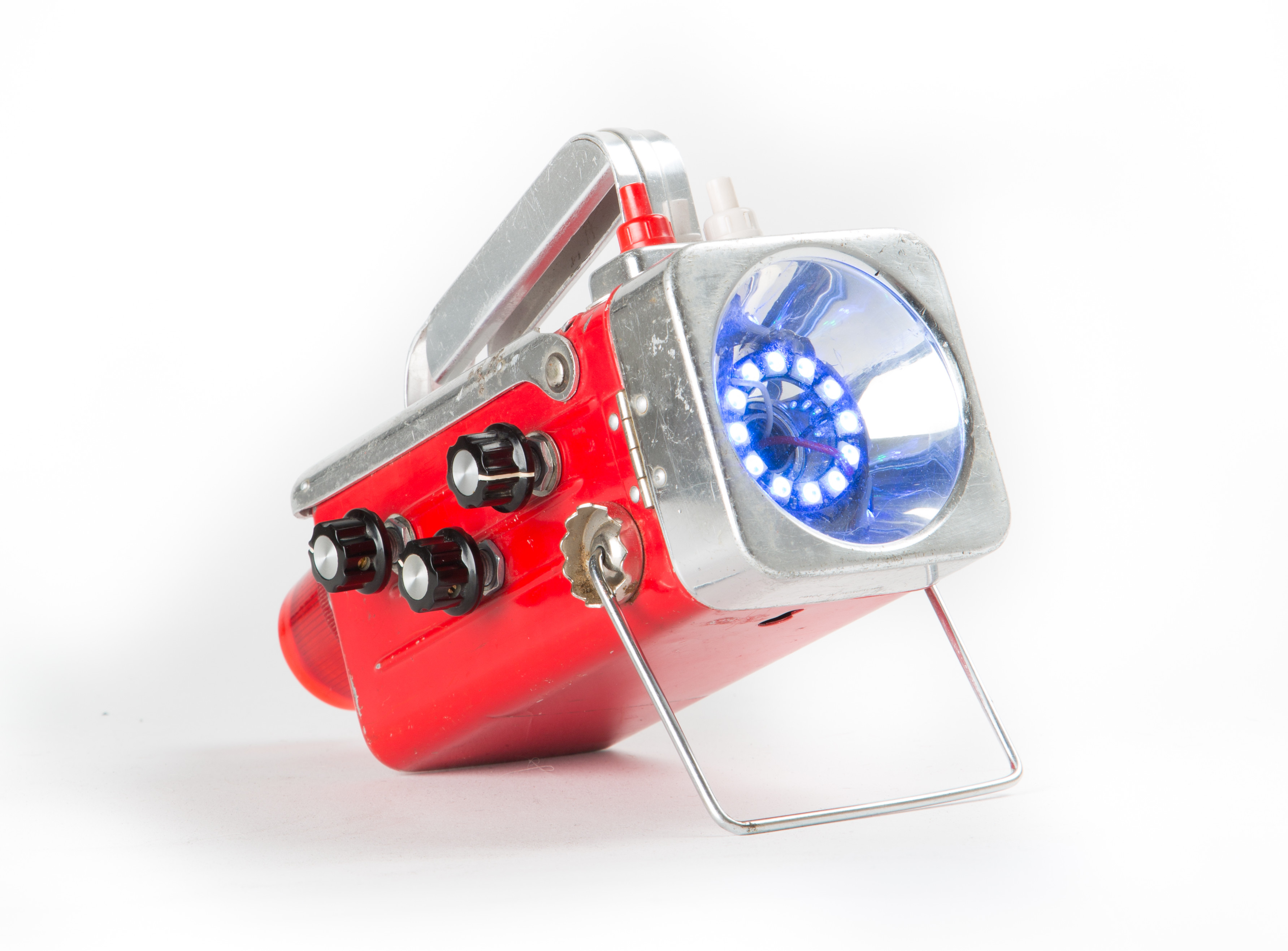
In this project we hack an old 6-volt lantern to become our Million Color HSL Flashlight. It’s big and bulky and different. Not quite as bright as some, but it has crazy color that’s so easy to set — just dial your way around the rainbow. Lots of knobs and modes, and you can write code for it too. Build it, turn it on, and experience its endless fun. Heck, if you take some time to make it watertight, you can inspect the levee with it too.
The great thing about HSL is that it’s an intuitive way to select a color. HSL stands for Hue, Saturation, and Lightness. This is like the 360-degree color pickers available in many computer applications. Our flashlight has a knob for each of these HSL components. Hue selects the color by allowing you to dial your way around the rainbow. Saturation selects how deep and rich the colors are: fully desaturated is white, fully saturated is pure color, anywhere in between is just that. Lightness behaves like a dimmer.
Our flashlight also has a 10-position mode switch. This is where the most fun comes in. You can select between 10 modes; check out the video for a demonstration:
- White
- Manual HSL
- Auto Hue: The light rotates automatically through the color spectrum (hue knob controls speed)
- Multi-color all-pixel auto-rotate
- Multi-color tri-pixel auto-rotate
- Cylon (aka Larson Scanner)
- Full-color strobe
- Alternate pixel multi-color 180-degree color alternation
- Half moon multi-color 180-degree color alternation
- Alternate pixel pair multi-color 180-degree color alternation
[wpvideo BENJmPci]
Hardware
Arduino: It’s a great platform for prototyping your projects. Once I’m ready to build, though, the standard Arduino board is kind of big, its jumper wires provide only fragile connections, and I want to free it up for my next project. Designing a custom board is time-consuming and expensive. The solution for many projects is to use one of the small Arduino boards available. I used the Arduino Pro Mini and it was perfect for this project. It’s inexpensive, very small, and reliable.
NeoPixel: In my search for bright RGB LEDs, I came across the Adafruit NeoPixel family. Two things make them perfect for this project. First, they’re available in different sizes and shapes, including the 12-element ring used in this project; it fits perfectly in the reflector bowl in most old-school 6V lanterns. Second, NeoPixels come with an Arduino library that’s easy to integrate and use for a project like this.
6V Lantern: The old-school 6-volt lanterns provide a perfect platform for this project because the reflector bowl and the battery compartment are both huge. Cool old lanterns are fairly easy to find and inexpensive at flea markets or eBay, but you can also buy new ones.
Where am I suppose to download the Arduino sketch from??
Hi Jim, Sorry that link is broken, will be fixed shortly. Meanwhile you can find it here: http://retro-tronics.com/HSLFlashlight/HSLFlashlight.ino
Links are fixed now, thanks Jim. Enjoy the build, it looks like a lot of fun!
I started freelancing online, working basic jobs which only requires from you a PC and internet access and I am so happy with it… After six months on this job and i earned in total 36,000 dollars… Basicly i earn 80 dollars/hour and work for 3-4 hrs daily.And the best part about it is that you get to choose yourself when to work and for how long and you get a paycheck weekly. -> Extra cash opportunity! <-
Awesome project Daniel! I used a 16 LED neopixel ring instead of the 12 you suggested. I forgot about the discrepancy when I first booted it up and I thought that I had 4 LEDs broken on my neopixel (see pic). Once I remembered, and due Daniel’s clean/commented code, I was able to change the PIXEL_NUM from 12 to 16 and add 4 elements to a few arrays found throughout. Oh and one conditional statement need to be updated also. Thanks Daniel! Cheers, Shalom
I thought I’d share the beginning of my triRotate edit (which would be more appropriately named quadRotate now) since I think it was just slightly more complicated than just changing 12 to 16 and adding some array elements:
void triRotate(float pot1, float sat, float val)
{
static float color1 = 0.01;
static float color2 = 0.26;
static float color3 = 0.51;
static float color4 = 0.76;
static unsigned int lighted_pixel1 = PIXEL_1;
static unsigned int lighted_pixel2 = PIXEL_5;
static unsigned int lighted_pixel3 = PIXEL_9;
static unsigned int lighted_pixel4 = PIXEL_13;
In addition to getting this segment working with 16 pixels, the digital pin definitions for the 10 position switch do not match the article instructions at all. I’ve made changes to the code that should technically allow any size WS2812-WS2811 ring to be used as long as the appropriate arrays are enlarged. Here is the link to my working code:
https://drive.google.com/file/d/0B1Q-zobluD7JSG94VWIwS0QtOEU/view?usp=sharing
Dan
Thanks for the fun project. I used the same Eveready lantern, but thought I would use the six volt lantern battery. I mounted the switch, pots and Pro Mini in the handle. This fed by a 4 wire plug and cable to the reflector. The 16 LED NeoPixel Ring fits nicely around bright white LED bulb. It was a challenge putting the parts in the handle – the place where your fingers would normally grip the handle is filled and will be enclosed by plastic walls.
Hello I am almost done with this build and am quite excited about seeing it in action.. Only problem, I am not seeing anywhere what to do with the black and orange wires from the 3 pots.. And as to the cap, I, I am assuming I could just place it across the battery terminals?? Ugh..
It’s described in step 11. Tie all vcc (Orange) and ground (black) together. As for the cap, across the red and black wires of the battery pack is correct.
I got a new plastic 6-volt lantern for this project, but I can’t see how to get into the reflector bowl area. It seems to be glued down inside the clear plastic cover. I don’t want to break it! Any advice on how to separate the bowl from its clear cover?
You’ll just have to figure a way to cut it. You could use a band saw or a hand saw to sever the narrow portion of the cone from the assembly, but that will be hard to do and likely dangerous. In our lantern, there were 4 holes in the metal mounting bracket where plastic from the cone was melted to connect the two together. A few seconds with an appropriately sized drill bit in a drill press and we were able to drill out the plastic and separate the cone from the mounting plate. I hope this helps.
You never explain what the headers are for or what cable you use to connect the arduino board to the PC. That cable you show in the picture isn’t listed in the parts (that I can see anyway).
I’m confused about the power requirements. As I mentioned in
my previous post, you don’t explain anything about why I’m connecting headers
to the board or how I connect the board to the computer (the cable is shown in
the pictures, but isn’t described anywhere in the article). Because of this, I
had to grab a different board, one that has a USB connector for downloading
code. I have a Teensy board and a Adafruit Pro Trinket. The problem is that the
instructions describe connecting two different power inputs and these boards I
have only have one battery input. What do I do?
I don’t understand the how the raw and regulated power inputs are used
differently in this project.
Also, the instructions called for a 4 AA battery power
source, but the images in the articles show a 9v battery connector. Are both
used? The 9v battery is not listed in the parts list nor mentioned in the article.
In step 7 you have us connecting the raw power wires which includes
the red wire from the battery pack but then in the next step you have us
cutting the battery pack wire and soldering it to the switch. That’s duplicate
use of the red wire from the battery pack and isn’t making sense to me.
Can someone please clarify this for me? Can I just connect all of the red and orange wires to the single voltage input on the boards I have? Or, if I have to use the other board, the one described in the article, what type of cable do I need to connect to the computer?
I might be able to help a little. The headers are for hooking up the
board to the computer thru the FTDI cable but if you are cheap like me,
the board may need a cable that uses a CH340 driver and cable instead ( You can get cheaper boards on ebay but they might use a different chip that
doesn’t work with the FTDI cable but does work with the CH340 set up).
This was the hardest part of the build for me. Finally found the right
driver
and was able to upload the program. As for the raw and vcc wires.
There should be 1 vcc wire from the board soldered to the 3 wires off
the pots ( orange wires in above project.) The raw wires (red above )
should be soldered together. The orange and red wires should be separate
and not all soldered together. The Pro Trinket board you are using
could be 3v or 5v, make sure you have the 5v one. The 4 AA battery
holder Radio Shack sells also comes with a 9v plug that plugs into the
plastic 4AA holder.
Thanks, that helps. After I posted that, I went online and figured out how to connect the computer to the board and what kind of cable I needed. I was just really disappointed that the author told me to connect headers, but not where or why then completely ignored explaining how to connect the computer to it.
You missed what I think is the most important question for me. In step 7 it tells me to connect the red wire from the battery pack to the other red wires, but then in step 8 it tells me to connect the red from the battery pack to the switch. I can’t do both, so what should I be doing here? See what I mean? He’s using the red battery pack wire twice and that’s not making sense.
Sorry, it’s step 11 here but I think step 7 in the magazine.
Solder the red wires together like it says in step 7/11. You’re now going to have to cut the red wire from the battery clip in half, strip both ends and solder them to the 2 poles on the on/off switch. I used a different switch than what was on the lantern. You might need extra wire to do it. You can also solder the red battery clip wire to one side of the switch and then solder a wire from the other side of the switch to the cluster of red wires.
OK, that is what it’s saying, isn’t it? That just seems like a weird way to do it – why solder the battery pack to the red wires only to cut it later and splice in something else? I simply soldered two red wires to my switch then connected one to my battery pack and the other to the bundle of red wires. That worked for me and seemed like a cleaner solution considering how short the battery pack wires are.
How did you solder in the capcitor? He said to do it, but I wasn’t clear where to put it. Did you put it across the + and – pins on the neopixel or somewhere else? That part seems like an afterthought – he said it was important, but then said should and didn’t include a photo that showed it. I didn’t put it in and the light works great – since the code doesn’t send any power to the neopixel until after it’s blinked the light 5 times, it seemed unlikely there would be a surge.
I have an error message when compiling. No such file/directory for Adafruit_NeoPixel,h when going through verify/compile step. New to Arduino, did I miss a step?
You have to install the Adafruit_Neopixel.h library in the arduino program. go to https://github.com/adafruit/Adafruit_NeoPixel and follow instructions.
Here is my version. I happened to have the projector lens lying around. One thing led to another. Thanks Dan!
https://youtu.be/agWwKX6kr_U
I am not sure what to do with the black wire from the 10 pos switch “c”.
I used a potentiometer over the 10-pos rotary switch – divided the analog reading by 100 and cast it to an integer – this gives you values 0 to 10. I then modified all the if’s. Cuts the need for 10 wires and 10 digital inputs…. thanks for this write-up and code – I really love my new/old flashlight
I have made a .NET Microframework (ported it to C#) version of the flashlight. https://www.ghielectronics.com/community/codeshare/entry/1057
https://www.youtube.com/watch?v=fwHu3JA60cU
I’m drowning! Help. I have jumped into this project and I simply can’t get it to work.
I have…
1. Arduino Pro mini connected and successfully uploaded with the right sketch. – Success!
2. The hardware connected, checked, rechecked, ripped out and started over, rechecked, thrown in the trash and new parts, started over, and rechecked.
3. New batteries
4. new switch
Still no luck.
When I power it on the Arduino board has 5 green led flashes and the red led in the center stays on continuously. The Neopixel ring has 3 LEDs that flash one time, and then nothing. No change from any position in the pots or the 10way switch.
I checked the continuity from each solder point and have no breaks in wires or bad solders.
The neopixel ring is not touching anything. It is suspended in mid-air by its wires so it can’t short out.
The metal case of the pots and hardware are not touching.
I am using the parts off the list in the instructions and have bought them all twice now, some of them 3 times. This is the second Arduino just in case I burnt out the first one or it was possessed by bad voodoo. I am way over committed to this. I must get it to work. I’m just mad at this point, really mad.
I am new to electronics and there must be something that everybody else knows that I don’t.
I had one point of confusion in the instructions that took me some time to learn about and understand. Perhaps I understand it wrong.
The part where you are instructed ” Before connection a neopixel strip to power, connect a large capacitor (1000uf, 6.3v or higher) across the + and – terminals…”
The cap that I have is 1000uf 10v. That seems to fit the description to me.
Is there a direction to connect the cap?
ie…
1. the + going to the neopixel should connect to the + of the cap and the – of the cap to the ground
or
2. the + going to the neopixel should connect to the – of the cap and the + of the cap to the ground
Please help me.
Substitute a rotary encoder for the 10-position switch (easier to find and cheaper on Ebay.) This way you have far fewer wires to deal with. Add an 8-pixel ring inside the 12 (http://www.ebay.com/itm/121710461262 is 32mm outside diameter. http://www.ebay.com/itm/121733541808 is 35mm inside diameter. Should nest perfectly. You could cut a piece of thin plastic to mount them to so the 8-pixel one has support. Party plates from the dollar store would work fine for that.) If you power up all 20 LEDS full brightness, you’d get around 4w of power out of them.
Of course the programming would need to be modified a bit but with a rotary encoder, since it’s basically unlimited positions, you could make one set of patterns that use just the inner 8, another set for the outer 12 and a 3rd set for all 20.
Easier yet might be 2 small push buttons. Press one repeatedly to go up through the cycle of patterns and the other to go down (push buttons can be much smaller than a 10-position switch but give the tactile feedback that a rotary encoder lacks.)
FYI – The link to the code has moved to here (I no longer own the retro-tronics domain): http://dkrasmussen.com/HSLFlashlight/HSLFlashlight.ino
I have an arduino nano instead of the pro mini, is there a program out there that would work with it. It’s reading that, ” adafruit neoPixel.h No such file or directory” I really need some help guys.
ConfigureACCEPT
Privacy Overview
Necessary cookies are absolutely essential for the website to function properly. This category only includes cookies that ensures basic functionalities and security features of the website. These cookies do not store any personal information.
Any cookies that may not be particularly necessary for the website to function and is used specifically to collect user personal data via analytics, ads, other embedded contents are termed as non-necessary cookies. It is mandatory to procure user consent prior to running these cookies on your website.