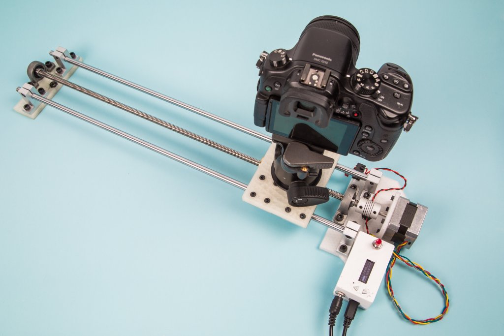
I’ve enjoyed capturing timelapse videos ever since I found myself in possession of a camera that could do them. I love the way they transform the mundane into the surreal, whether it’s the ability to see a transformation taking place that’s too slow to observe with the naked eye, or to witness the haphazard nature of our daily lives unfold at breakneck speed. I even carry a small tripod kit with me wherever I go so I can film them with my phone when I have a short wait.

The best way to take your timelapse videos to the next level is to move the camera while it is capturing them, but this is tricky to do unless you have some sort of fancy motion controller. A few years ago, I designed a device that allowed you to pan a camera while it was capturing a timelapse. It was great, but I really wanted the ability to translate, or dolly the camera through space, as it was filming. Years later, and after many ill-conceived and half baked prototypes, I’ve finally built one.

This motion control camera slider will allow you to capture timelapses of anywhere between 5 minutes and 8 hours, and has a span of roughly 500mm. The control unit, motor, and slider mechanism are completely self contained and don’t need any other devices to program the motion.

Project Steps

Get Printing!

All of the parts printed: Drive Plate, Driven Plate, Carriage, Housing and Buttons

There are a number of printed parts to this, and they’re all fairly large, so it’s good to get this started first. You can find the files over at GitHub. All of the parts in my design were printed in PLA to help maintain their dimensional accuracy. I printed all of the parts using a .8mm nozzle to cut down on print time and improve part strength. I printed using 3 layer walls and 35% cubic infill, and they’re quite strong.

The large parts don’t need to be pretty, just strong. Use a .8mm nozzle for strength & speed.

The “Drive Plate” part should be printed using a .4 mm nozzle to help preserve the finer details. The stepper motor also gets quite hot during operation, so printing this in a heat-tolerant material like ABS or HTPLA is a good idea. The motor gets hot enough for the PLA to become pliable by hand, but not hot enough for it to fail. Still, this may be a consumable part.

Solder Everything

The three boards soldered with headers & terminals.

Start by soldering the headers onto the boards. The OLED Featherwing gets the standard solder pins, pointing down. Using a breadboard to keep everything straight and steady while you work is a great idea. Snap the wire terminals for the Motor Controller together before soldering them to the board. There’s a few wire connections to make to the Motor controller as well.

Pushbutton (Yellow) and Endstop Switch (Red) soldered to the underside of the Motor Controller

Solder a short length of wire to pin 11 for the Endstop switch, and another to pin 6 for the momentary pushbutton. Then add the stacking headers to the motor shield. Finally, solder 2 ground wires from both switches to the proto board ground rail, then add the stacking headers & trim off the header pins sticking out the bottom of the board.

Motor Controller with everything wired up.

Solder the DC jack to a short pair of wires. Strip and tin the other ends before securing them into the terminal block of the motor shield. Wire up the motor to channel 2 of the motor shield, in this following sequence: red, yellow, green, grey. If you’ve sourced some other motor, or your motors are wired with a different set of colors, you’ll need to identify the coil pairs on your own, using one of these helpful tutorials.

Assemble!

Press fit the 1/4 20 nuts into the two baseplates

Start assembling the 3D printed parts in following order. Press fit the two ¼ 20 nuts into their receptacles in the two baseplates. They’re intentionally a fairly tight friction fit, if you have a tough time getting them to press in, thread in a bolt from the bottom of the baseplate and use it to pull the nut into the hole, and then unthread it once the nut is properly seated.

Motor and Endstop switch mounted to the drive plate.

Use the four m3 screws to attach the motor to the drive baseplate, and then use the m2.5 screws to attach the endstop to the the same baseplate. Use the same M3 screws to attach the 32u4 protoboard to the baseplate. Attach the shaft coupler to the motor shaft, making sure to align one of the set screws with the flat spot on the motor shaft. Then, use the m5 screws to attach the pillow bearings and rod brackets to the baseplates.

Protoboard mounted using the m2.5 screws
Pillow Bearing and Rod Brackets mounted to the Drive Plate

Next, assemble the carriage. Press the ⅜” bolt through the bottom and seat the cap into the hexagonal recession. Press the lead screw nut into the front of the carriage plate. It’s a fairly tight fit, so using a bench vise can help to press it in.

Hardware installed into the carriage plate. Note the loose m4 screws on one side.

Use some scrap wood to protect the lead screw nut from the vise jaws. Attach the linear bearings using the m4 screws, but keep one side loose – this will help align them to the rods. Thread the lead screw into the nut and then slide the rods through the linear bearings.

Lead Screw and rods installed on the carriage.

Fit the threaded rod through the pillow bearing and into the coupler, and then follow with the rods into the brackets on the drive plate. Finally, fit the lead screw and rods into the bearing and brackets on the other plate. Tighten everything up, making sure that everything is straight and perpendicular, and finally tighten the remaining screws on the carriage.

Everything is installed!

Code!

If you haven’t already, fit the motor controller and then the OLED wing onto the protoboard. You can get the sketch at the repo for this project. Upload the code to the board using the IDE. You’ll likely need to install a number of libraries to support the OLED screen and the motor controller. Once the code starts, the first thing that should happen is a homing sequence for the motor. Tap the endstop switch to make sure that it completes the homing sequence. If it does, then power the motor using the 12v supply and restart the board using the reset key. Let the carriage home itself, and then measure the distance, in millimeters, from the carriage to rod bracket on the far end. Take this measurement and multiply it by 25. Find the variable spanLength near the top of the sketch and replace it with the number.

Upload the code again, and then fit the housing over the electronics, thread in the DC jack and pushbutton and then secure the housing using 3 m2.5 bolts from the bottom of the baseplate.

Use it!

When you power the slider on, it should first perform its homing sequence. From there, just adjust the timer for the length of the timelapse you want to record, and get your camera running. Once the sequence starts, you’ll see a progress bar and countdown timer. When the sequence is complete, the carriage will re-home and start again. If you made a mistake, just punch the reset button through the hole in the top of the housing.


Taking it Further

It’s great to finally have this project off of my plate, but there are a few places I’d love to improve on it. The lead screw drive system is absolutely solid, but it’s also far too loud to use for realtime use around microphones. I’d love to see if it sounds better with some motor damping, or with a belt driven system. The motor also gets very hot in operation, and that’s a bit of a worry. The temperature tapers off at about 60 degrees Celsius, which is plenty hot enough to be uncomfortable. I’d also like to be able to power everything with just the 12v power jack, instead of needing the additional USB power source. But there’s always room for improvement.