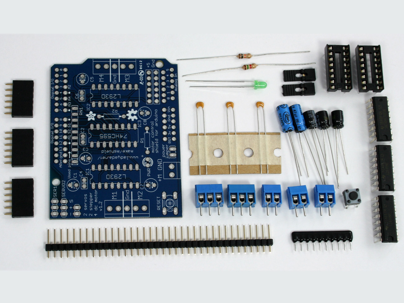
Arduino is a great starting point for electronics, and with a motor shield it can also be a nice tidy platform for robotics and mechatronics. The MAKE MotorShield Kit, designed by Adafruit Industries in partnership with MAKE, is a full-featured motor board that can power many simple to medium-complexity projects. It’s got:

  • 2 connections for 5V “hobby” servos connected to the Arduino’s high-resolution dedicated timer — no jitter!
  • Up to 4 bi-directional DC motors with individual 8-bit speed selection (so, about 0.5% resolution)
  • Up to 2 stepper motors (unipolar or bipolar) with single coil, double coil, interleaved or micro-stepping
  • 4 H-bridges: L293D chipset provides 0.6A per bridge (1.2A peak) with thermal shutdown protection, 4.5V to 25V
  • Pull-down resistors keep motors disabled during power-up
  • Big terminal block connectors to easily hook up wires (10–22AWG) and power
  • Arduino reset button brought up top
  • 2-pin terminal block to connect external power, for separate logic/motor supplies
  • Tested compatible with Arduino Mega 1280 and 2560, Diecimila, Duemilanove, and UNO

Get your MotorShield kit from Maker Shed and build it in a couple hours, following the instructions here.

Then download the easy-to-use Arduino software library and you’re ready to go!

Project Steps

Gather your parts and supplies.

Check your kit against the parts list so you know which parts are which.

Gather the necessary tools for assembly in a place where you can safely use a hot soldering iron.

Place the MotorShield PCB in a vise or other circuit-board holder and heat up your soldering iron to 700°F.

Solder the resistors.

The first parts to go in are the 2 resistors, R1 (1.5K, Brown Green Red Gold) and R2 (10K, Brown Black Orange Gold).

Bend the resistors’ wire leads straight down so they look like staples.

Next, slip the resistors into the printed circuit board (PCB) as shown, so they sit flat against the board. Bend the leads out a bit so they’ll stay put when the board is flipped over.

Resistors are not polarized, which means you can put them in “either way” and they’ll work just fine.

Using your soldering iron tip, heat the resistor wire lead and the metal ring on the board (the pad) at the same time. After a few seconds, poke a little solder in so that it melts into a nice cone. Remove the solder, and then remove the soldering iron. Do this for all 4 wires.

Check your work. You should have clean solder joints.

Clip the long leads just above the solder joint using diagonal cutters.

Solder the ceramic capacitors.

Next place the 3 yellow ceramic capacitors C4, C2, and C6. Ceramic capacitors aren’t polarized either, so you can put them in either way.

Bend the leads out just like you did with the resistors.

Solder all 6 wires, then clip them as you did with the resistors.

Solder the reset switch and resistor network.

Next is the 6mm tactile switch, marked RESET on the board, and the resistor network RN1. The tactile switch is used to reset the Arduino since it’s not possible to reach the reset button once the MotorShield is on top.

The resistor network is used to pull down the pins on the motor driver chips (so they read LOW), so that they don’t power up the motors before the Arduino sketch tells them to.

The tactile switch can go in either way. The resistor network, however, must go in a certain way. Make sure the end with a dot is positioned at the same end as the X in the silkscreened image of the resistor network on the board.

Flip the board over and solder in the resistor network and switch. You won’t need to clip the leads as they are quite short aleady.

Install the integrated circuits (ICs).

Next are the 3 integrated circuits IC1, IC2, and IC3. When ICs come from the factory, the legs are angled out somewhat, which makes it difficult to insert them into the PCB. Prepare them for soldering by gently bending the legs against a flat tabletop so they’re perfectly straight.

NOTE: This kit comes with two 16-pin sockets for the L293D motor driver chips. These sockets are optional and not necessary for operation. However, if you are not experienced with driving motors (your likelihood of wiring up a mis-specified motor is high), you should install the sockets, so if the L293Ds are destroyed you can easily replace them.

If you’re experienced with driving motors, you may want to skip the sockets as they decrease the chips’ heat-sinking abilities.

ICs must be placed in the correct orientation to work properly. To help with placement, each chip has a U notch at the top of the chip. On the circuit board there is a printed out image of the chip outline and one end has a U notch. Make sure the chip notch is on the same end as the image notch. In this PCB, all are facing the same way.

Gently insert the 3 chips (or the 74HC595 chip and the 2 sockets). Check to make sure none of the legs got bent or broken. The 74HC595 goes in the middle, and the two L293Ds go on either side.

Solder each pin of the chips and/or sockets.

If you’re soldering the L293D motor driver chips directly, note that the 4 middle pins are tied to a large heat sink and thus may end up getting bridged with solder as shown in the third image.

Solder the electrolytic capacitors.

Next are the three 100µF electrolytic capacitors C1, C3, and C5.

CAUTION: Electrolytic capacitors are polarized and must be placed in the correct orientation or they could pop!

The long leg of the capacitor is the positive (+) leg and goes into the hole marked with a +, as indicated in these close-up photos.

NOTE: Capacitors are not color-coded. The body color can vary from blue to violet to green to black, so be sure to read the value on the side — don’t depend on the color!

After double-checking their polarity, solder and clip the 3 capacitors.

Solder the electrolytic capacitors, cont'd.

Place the two remaining electrolytic capacitors, the 47µF caps C7 and C8.

Again, these are polarized, so make sure the long lead is inserted into the + hole in the silk-screened image on the board.

Again, capacitors aren’t color-coded, so be sure to read the value on the side, and don’t depend on the color.

Solder and clip the 2 capacitors.

Solder the LED.

The 3mm LED is used to indicate motor power. LEDs are polarized, just like capacitors, and the long lead is the positive (+) lead.

Make sure the LED is placed correctly, otherwise it won’t work!

Solder and clip the LED leads.

Make the headers.

To make the headers for the jumper, servos, and Arduino, we use one stick of 36-pin “breakaway” header, and break it apart to make smaller strips. You can use diagonal cutters or pliers to snap off the pieces.

Break the 36-pin header into two 8-pin, two 6-pin, two 3-pin and one 2-pin headers.

NOTE: If you have an Arduino NG (an older board), you may want one 6-pin header and one 4-pin header instead of two 6-pin headers.

Solder the small headers and terminal blocks.

Place the two 3-pin headers in the servo connections in the top left corner. Place the 2-pin header in the power (PWR) jumper in the bottom center.

Also place the large screw terminals for the motor and external motor-power wires. Place a 2-position terminal block at the bottom left of the board, and place the remaining 2- and 3-position terminal blocks together to make the two 5-position terminals.

Solder in the 3 small headers and all 5 terminal blocks.

Solder the large headers.

Next, place the 8-pin and 6-pin headers into your Arduino board. This will make sure that the headers are perfectly lined up. Make sure the Arduino is not plugged in or powered!

Place the MotorShield on top of the Arduino, making sure all the header pins line up in their proper holes in the shield.

Solder each header pin into the MotorShield.

You’re done! Now use it!