This guide is intended to show you how to build the Pendulum Challenge Kit from the Maker Shed. The build involves soldering and should take less than half an hour. This is a good, fun project for beginners that is as fun to build as it is to play.

What will the next generation of Make: look like? We’re inviting you to shape the future by investing in Make:. By becoming an investor, you help decide what’s next. The future of Make: is in your hands. Learn More.

Project Steps

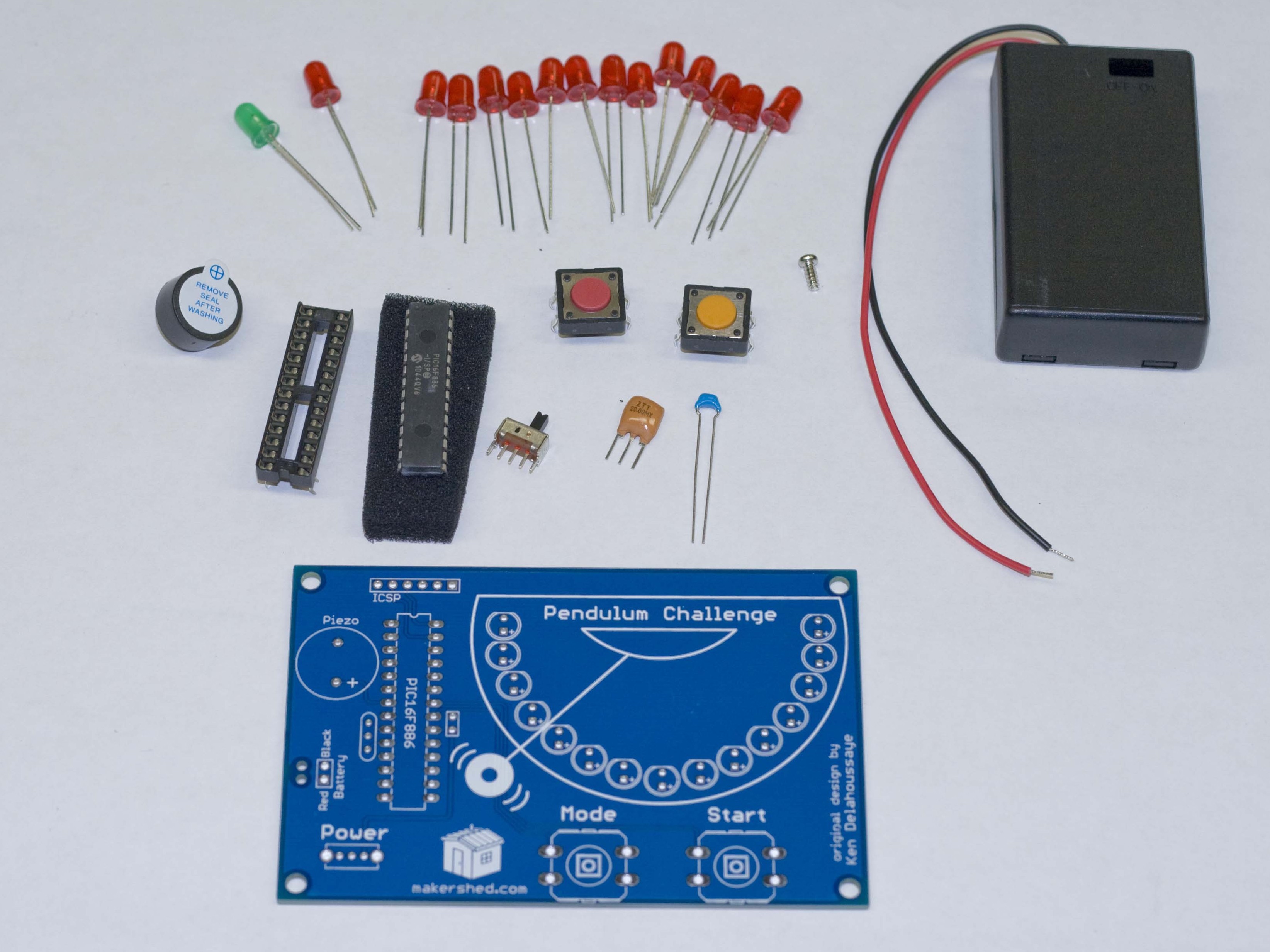
Before I build something I typically dump out the contents and lay everything out. This makes it easier to find what you’re looking for and lets you know if you’re missing anything. The pendulum challenge kit has 26 parts including the screw for the battery cover.

First, let’s isolate the PCB (printed circuit board). It’s the big blue flat thing with white writing. All your components attach to this so it’s pretty important. Orient it just like the picture.

Find the IC holder from your parts collection. It’s the thing that kind of looks like a microchip but isn’t. This is where the microcontroller plugs in. Notice how one end has a little notch in it? This is a directional part and must be inserted notch side up, just like the outline on the PCB.

Next, insert the IC holder notch side up just like the outline. Be sure that all the little legs go into the corresponding little holes!

Now in order to solder the IC holder, you are going to have to turn the PCB over to the back side with the IC holder still in place. If you bend a couple of the legs outward the IC holder won’t fall out when you flip the board over. Once you bend the legs out, go ahead and flip over the board and solder the legs to the PCB.

Once all the legs are soldered in place you can clip off the excess with some side snips. You don’t have to do this (there isn’t much extra there to snip).

Now, obtain the green LED. Not a red LED, the GREEN one. You’ll notice that one leg is longer than the other. The long leg is positive. (I remember it as long = more = plus. :) Place this LED into the hole for it in the center of the layout, long leg in the + hole.

Just as with the IC holder, spread the legs of the LED out on the back of the board so you can solder them into place.

Finally, snip off the excess with your handy side snippers. Watch your eyes!

Go ahead and populate the rest of the holes with the red LEDs. Remember, the long leg goes in the “+” hole! Spread the legs out on the back of the board as you go.

After you get the LEDs in place, turn the board over, solder, and clip the excess. I don’t need to remind you to watch your eyes again, do I?

Now, on to buttons! There is a yellow-ish button and a red-ish button. Both are functionally the same so you can use either one you want for start and mode. I used the red-ish button for mode and the yellow-ish one for start. The legs are shaped so they happily snap into place.

Snap in the buttons, turn the board over, and solder away! Again the buttons have short legs so clipping is optional. I clipped mine just for fun. Remember the eye thing?

Let’s take care of the resonator. It is brown-ish, has three legs, and has the words “ZTT 26.00MX” on it. It doesn’t matter which way this goes in so put it in place to the left of the IC holder.

Bend the legs, flip over the board, solder and clip. (EYES!)

Now we are going to put in the capacitor. It’s the little blue thing. It has some writing on it but I am not going to read it since it is the only blue thing in the kit that isn’t the PCB.

It isn’t a directional component so put it in place opposite the resonator, on the right of the IC holder.

Bend the legs, solder, and clip! (I would remind you about something but I think you’ve got it by now.)

Now for the power switch. It looks like, well, a switch! Put the legs into the holes any way they fit.

It’s hard to bend these legs so just use a finger or the handle of your snippers to keep the switch in place as you solder.

Since the legs are short, snipping is optional.(Cough *eyes* cough.)

Since we’re making a game, we are going to want it to make some noise. The speaker is round, has two legs, and has a sticker on the top saying something like “remove after washing.”

You’ll notice the legs are uneven, like the LEDs. Remember what this means? Yep, the longer leg is positive so be sure to put it in the “+” hole, bend the legs a little, solder, and clip. (I’m not going to remind you about the eye thing.)

This is the easiest step of the project. Remove the sticker and stick it on a friend, dog, or in the trash. The trash is probably the best choice but the least amount of fun.

What good is a game without batteries? Find the battery pack (it’s the big black thing with two wires that looks like a battery pack.) Feed the wires up through the bottom of the board through the appropriate hole (red to “Red,” black to… you get the idea.)

Loop the wires over and put the shiny, stripped end into the appropriate hole. Gently pull the slack out of the wires until the loop pretty much disappears.

Now turn the board over and solder the wires. Clip off any excess. (I’m done reminding you about your eyes.)

Just to make life easier, I put a bit of foam tape (not included) on the back of the battery holder, then stuck it onto the back of the game. This is optional but really, really, handy.

Be sure to put the tape on the side opposite the battery cover.

It’s time to put in the microcontroller. It looks like a black rectangle with lots of shiny legs. It’s probably stuck into a bit of foam so go ahead and pull it out.

Like the IC holder, the microcontroller has a notch at one end. This notch needs to be oriented the same as the notch on the IC holder and the outline on the board.

Unfortunately, the microcontroller isn’t going to fit right into the IC holder without bending the legs in a little. This is easiest to do by holding the microcontroller by each end and gently “rocking” the legs against a flat surface like a table. Do this on each side gradually until the legs fit into the IC holder.

Finally, place the microcontroller on top of the IC holder paying UTMOST ATTENTION TO THE DIRECTION OF THE NOTCH! BE SURE IT MATCHES THE DIRECTION OF THE OTHER NOTCHES. I’M SUPER SERIOUS!

Gently press down on the microcontroller (rocking may be necessary) until it is seated into the IC holder.
Time for the last steps! Open up the battery holder and put in three AAA batteries. The screw is optional (I didn’t use it).

Turn the game over, turn on the switch, and play!

Holding the “Mode” button down for a few seconds will mute the sound. Use the “Start” button to begin the game and stop the pendulum on the green light. It’s a lot harder than it looks!

Now, sit back, play your new game, and bask in the awesome. You just made an electronic game! Congratulations!

I really hope you took my advice about the eye protection. If not, I guess you won’t be reading this. Sorry about that.

Conclusion

This kit is easy to build and provides hours of challenging fun!