It is a profoundly human compulsion to change our environment to suit ourselves, and the quarter-trillion-dollar US home décor industry presents a playful (and profitable) example: We bedeck our living spaces to express ourselves and illustrate our individuality. Colorful light displays decorate busy event spaces like concerts and sports arenas, but they can also function as enchanting home ornaments, like my LED Rainbow Weather Station (Make: Volume 69), and Inner Glow Edge-Lit Heart (Volume 71).
ILLUMINATING INTERIOR DESIGN

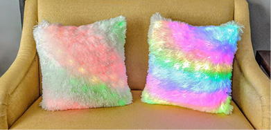
This LED matrix pillow project is not only pretty but practical as well. The electronics attach to a removable DIY pillowcase, so the outer decorative cover and stuffed pillow insert both may be removed for cleaning. You can change display colors and patterns, controlled by the codable Pixelblaze controller board, for both visual embellishment and entertainment.
There is something unexpectedly delightful about embedding electronics in soft, cuddly objects, and these sparkly pillows emphatically spark joy inside my home.
SPARKLY JOY
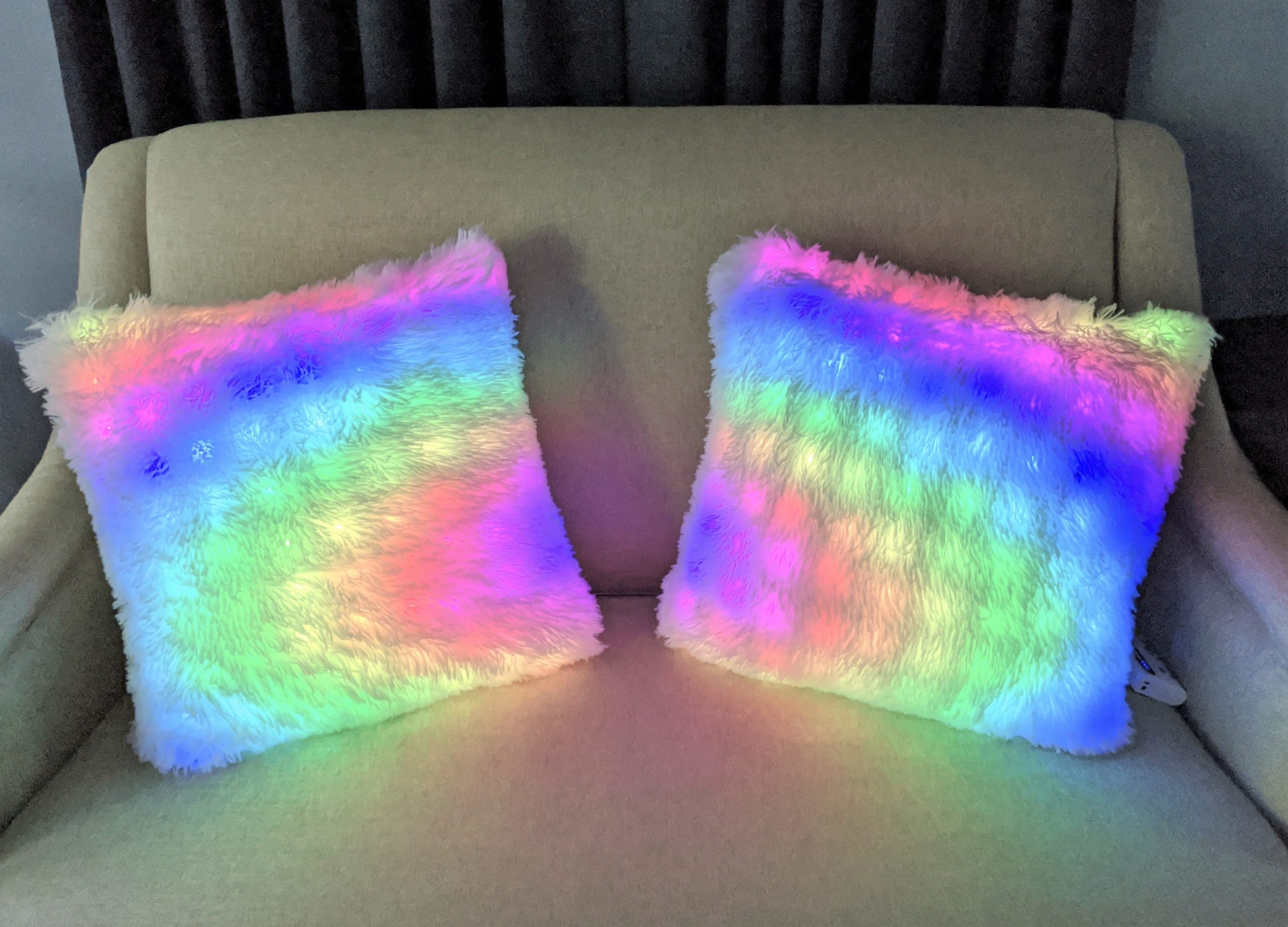
These pillows are a DIY project to display proudly. They morph from innocuous home accessories to something far more beautiful and interesting with the flick of a power switch. It’s hard for still photos to convey the dynamic beauty of constantly changing LED animations, but these pictures are a small example of what is possible.
They’re also extremely touchable and will stand up to a fair amount of abuse, because the weatherproof outdoor LED strings flex easily. I’ll stop short of recommending them for a pillow fight, but they will easily survive the use that normal throw pillows get (as long as nobody yanks hard on the wiring). And the covers unzip and can be removed for washing, so kids can absolutely touch them, hug them and enjoy them.


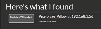
- Quick Start guide for the Pixelblaze V3
- The ElectroMage Forums are a great place to find inspiration and get questions answered
 ).
).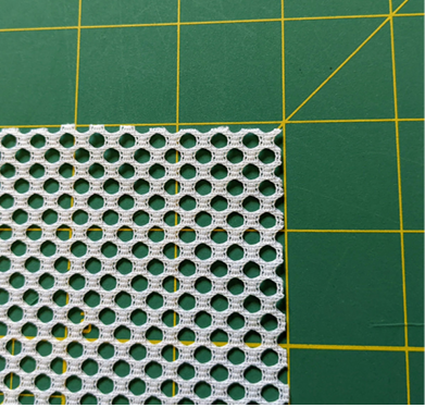
 ). Unfold the square and lay it on a flat surface with scratch paper underneath. Now use the Sharpie to draw two vertical marks that are 2.5cm on either side of the midline. Continue to draw additional vertical marks at 5cm intervals on both sides side until there are exactly 10 symmetrically spaced marks at 5cm intervals (Figure
  C).
C).

 ). Repeat this process with the second 21″ mesh fabric square.
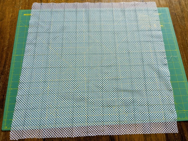
 E).
E).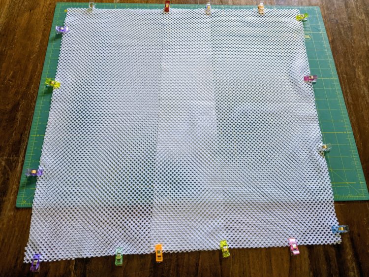
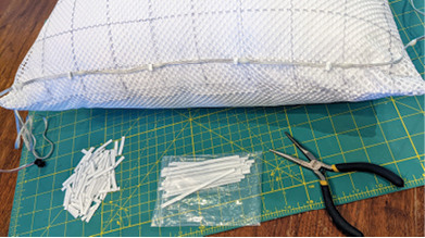
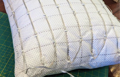
 ). Invert the mesh case through the center opening (Figure G
 ), pushing the corners out from the inside with your fingers. Insert a pillow insert into the mesh case, plumping and tugging the pillow corners to fill the case without slack.
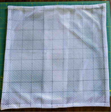
 ). The back is a bit flatter and noticeably dimmer than the front. Be careful to place the LEDs front side upward when securing the string in the next steps.
 ). Then, take the input end of the LED string and lay it along one of the border grid lines, aligning the LEDs with the intersections.
 ). The tie is slightly wider than the holes, so you may have to pull the mesh taut and wiggle it a bit to slip it through.
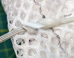
 ), then fold the opposite side of the tie extending from underneath the LED string to cover the first folded section (Figure L
 ). With the pliers, bend and crease the remaining overhanging twist tie section back underneath the string and tie, pressing it firmly to grip the wires inside. Tuck the final short segment into the mesh under the string (Figure M
 on the previous page).
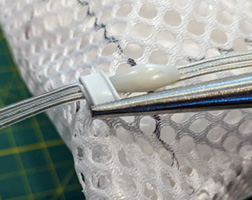
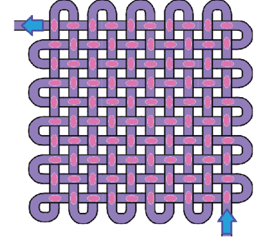
 ). At the end of the row, bend the string into a U-shaped turn and place the next LED in the closest adjacent row so that it is offset by one column from the previous LED (Figure O
 ). Proceed to fill all the rows using this technique until half the LED string is attached to the case in a zig-zag pattern with one folded twist tie near each LED. The LEDs should sit at alternate grid intersections, so that the LEDs in each row are offset by one from their neighbors (Figure P
 ). Double check that all LEDs have front sides oriented upward, away from the pillow.
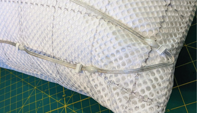
 .
.
 ) When you are finished, the LED string input/output connectors should extend from opposite pillow corners and the string will be woven into a pattern that looks like Figure
  S. You may wish to attach additional ties to affix any parts of the string that seem loose.
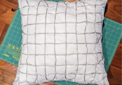
 , then connect an extra 3-pin JST-SM cable to the LED string input, and connect that cable’s Power, Data, and Ground wires to the corresponding screw terminals on the Pixelblaze.
 ).
).
 V). Assign your board a descriptive name. Set the LED Type to WS2812 and the Data Speed to 800 Kbps. If you are not sure of the Color Order, select GRB — if the colors in some patterns look wrong, you may have to experiment with this setting to find the correct option. Set the number of pixels to 200, for the two LED matrices. It’s a good idea to limit LED brightness in the settings to reduce power consumption and heat output. Specifying a maximum 25% power is usually more than adequate to generate a bright display.
 W). Download the code file
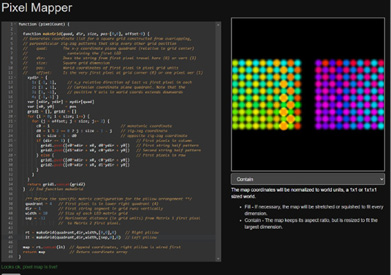
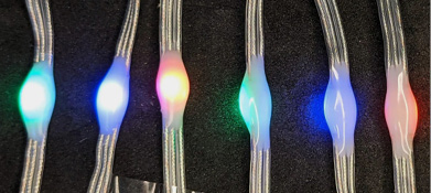
 shows the difference in appearance of LED light shining through (from right to left) no diffusing material, a single layer of batting, and a double layer of batting.
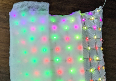
 ).
).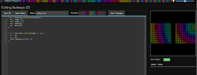
 ). If you’re not comfortable with jumping in to coding your own patterns, making small changes to existing code and watching the real-time display response is a great way to learn.