In 1976, Atari introduced Atari Video Music, a plugged-in music visualizer designed by Pong creator Bob Brown that bridged the yawning gap between consumers’ stereos and their TV sets. The quirky, psychedelic pixelation device never caught on, but watching it in action today (check it out on YouTube), one is taken back to another time, long before iTunes and Winamp visualizers. It was a time when vinyl, denim, Foghat, mood rings, limited color palettes, and RadioShack’s business model all somehow made sense.

And while Foghat’s career may be a distant memory, interest in Atari’s long-gone device remains. So we introduce the Pixelmusic 3000, a weekend project that pays tribute to those groovy times, and to a product that was either too quirky or too revolutionary to make it past its first year’s production run.

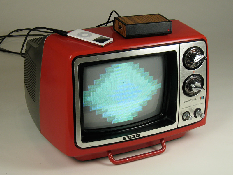
Today, of course, the technologies that enabled Atari Video Music are much smaller, cheaper, and more accessible. We’ll use the Propeller microcontroller and its video libraries to create a simple AVM-like visualizer that feeds a TV from an iPod or other music player. Check out a video of it in action here.

Project Steps

Make the cables.

Cut the stereo mini cable near 1 end, and strip the wires 2″ down. Use a multimeter’s continuity function to identify left channel, right channel, and ground (GND) wires, which correspond to the jack’s tip, ring, and sleeve, respectively. Ground may be a mesh surrounding the other 2 wires.

Cut the mini-to-RCA A/V cable near the mini end, then strip and identify the wires as you did with the stereo cable. This cable has an extra ring for video, which connects to the yellow RCA plug.

Solder the cable wires to the 3- and 4-pin circuit board headers. With the stereo cable, solder in this order: ground, right channel, left channel. With the A/V cable, follow the order ground, video, left, right. Confirm all connections with the multimeter — inside my possibly nonstandard A/V cable from a 99¢ store, the white and yellow wires were reversed.

Build the breadboard and test the circuit.

Insert the Propeller microcontroller, ADC, and EEPROM chips into your breadboard. I used 2 breadboard modules, with the Propeller over one centerline and the ADC over the other. As a rule, the top ends of the chips, indicated by a notch, should point toward the top of the board, like north on a map. Pins are numbered counterclockwise from top left. (However, I inserted the EEPROM chip upside down so I could ground its pins 1–4 in one move, using one of the breadboard’s bus strips.)

Chips ship with their pins slightly splayed, so before you put them into a breadboard, rock them on a hard, flat surface to turn the pins in slightly.

Follow the schematic to assemble the rest of the circuit on your breadboard using hookup wire. This lets you debug the circuit before committing it to solder. Other components include your 2 cables, a voltage regulator, a trimpot, a crystal, and a header for the Prop Plug programming port. I hot-glued the DC power adapter to the edge of the breadboard near the voltage regulator. Our LM2937 regulator has different pin assignments from the standard 7805 you may be used to, so check the datasheet on yours.

Both here and on the soldered circuit board, with few exceptions, I use blue wires for ground, red for power, and white, yellow, or black for other connections. Following a system like this makes the wiring easier and helps you visualize designing your own 2-layer PC boards.

If you haven’t done so already, install the Propeller Tool IDE (integrated development environment) on your PC. It’s a free download from parallax.com.

Run the Prop Plug from your PC’s USB port to the circuit, connect the DC power to the breadboard, and launch Propeller Tool. Hit F7 to confirm that it sees a Propeller chip. If not, check all connections, unplug and replug the Prop Plug, and try again. Standard debugging rules apply.

Download our pixelmusic.spin program file from pixelmusic, open the program in Propeller Tool, then upload it onto your Propeller by pressing F10. Presto! You can stop now, plug this thing into your TV and iPod, and have a personal dance party! The rest of this tutorial is just sweet icing on the cake.

Solder the circuit board.

Add the 40-pin socket to the board, over the centerline, and solder 2 corners down. You won’t solder every pin; on such a tight board, you only want to solder the pins being used.

Add the EEPROM and crystal. Orient the EEPROM upside down, with the pins nearest the notch (5 and 6) facing the bottom of the board and connecting to pins 37 and 38 of the socket. Wire pin 8 to the middle rail for power, and solder-bridge pins 1–4 together and connect them to the rail for ground. Connect the crystal to pins 30 and 31 of the socket.

For each connection, fill both holes with solder, then span them with a wire. Or for short straight runs with nothing in between, you can use a solder bridge. Test the continuity to confirm connections and check for shorts.

Add the 10kΩ resistor. Wire one side to EEPROM pin 5 and Propeller pin 38. Wire the other side to power and bridge the connection over to the EEPROM’s power pin, pin 8 (under the blue ground wire).

Add all remaining power and ground connections for the Propeller, following the schematic.

Solder the 4-pin programming header to the edge of the board and wire all of its connections.

Solder leads from the DC power adapter to the board, connect them to the voltage regulator, and add a 1μF decoupling capacitor between power and ground. I used a smaller nonpolarized cap to save space, but if you use an electrolytic, follow its polarity. Plug the adapter in and use your multimeter to confirm that you have identified power and ground correctly; reversing these will fry your chips.

You should now be able to program your Propeller through the perf board. Insert it into the 40-pin socket, making sure all pins seat correctly in the holes. Use a thumb on each side to press the chip down into place. Connect the Prop Plug to the board’s programming header, and connect the DC power plug to the adapter jack.

Run Propeller Tool on your computer and confirm that it can see the chip by pressing F7. Then reprogram the chip by pressing F10, and finally, upload the code to the EEPROM by pressing F11.

On the upper left of the board, solder and wire up the ADC chip and the trimpot, following the schematic.

On the lower left, follow the schematic to create and connect the resistor ladder (270Ω, 550Ω, and 1.1kΩ resistors) and the stereo and A/V cable headers. I used red and white wires on the topside of the board to send the stereo signals up to pins 1 and 2 of the ADC.

Use electrical tape and hot glue to provide insulation and strain relief on the cables, which you’ll bend pretty hard to fit into the case.

Connect a red LED to the circuit via a 2-conductor strip of ribbon cable. Wire the + side of the LED (the long leg) to Propeller pin 21 through a 270Ω resistor, and the – side to ground. The flexible cable lets you position the LED inside the case.

Build the box.

Measure the Serpac case for holes for the cables, LED, and power switch. Then carefully carve them out with a Dremel. I put the switch in one of the side panels. Then trace the case’s side panels on the contact paper, cut with a hobby knife, peel, and stick. Smooth!

Hot-glue the slide switch into the case and splice its contacts into the + power lead. Use more hot glue to fix the LED and cables in their holes and stick the circuit board to the case bottom. I contend that hot glue is integral to the success of this (any?) hacking project. It’s nonconductive, fast, and you can remove it easily if you make a mistake.

Build the box.

After confirming that the circuit works, screw the case closed, add rubber feet, and put on any finishing fake wood touches. Attention to detail is proportional to the amount of marvel in your friends’ eyes the first time they see your Pixelmusic 3000 in action.

Hook up and rock out.

The Television Connection: With any luck, you’re now the proud parent of your very own Pixelmusic 3000. Perhaps you stopped with the Breadboard 3000, or maybe you went all the way to enclosed-perf-board heaven. They both work. The PM3K sends a composite NTSC signal to the TV over the yellow RCA cable. Older sets, like the beauty pictured below, may not have a composite in (ours didn’t even have a coaxial in). Not to fear; just head down to any electronics store and get an RF modulator, which will convert the composite signal to 2-wire VHF antenna input on channel 3 or 4.

How to Use: There’s a sweet spot for visualizations. Too little volume and the shapes, patterns, and colors won’t change very much. Too much volume and things may change too frequently or be too big. Try playing with the input volume to find just the right level. You may also want to adjust the ADC’s trimpot to make big tweaks once or twice.

Mods and Rockers

The goal of this project is to create a retro rave in your living room, but the PM3K is portable too, so you can bring it to your friends’ parties and impress all the right people. It works with iPods, CD players, or anything else with a mini headphone output jack, and it’s just as fun with modern music and audio books as it is with classic album-oriented rock.

There’s plenty of room to mod your PM3K. The code is yours to tweak and revise, and it’s fun trying to create programs to run with the limited RAM and color budget that the Propeller allots. You might want to try adding some pots and switches; there are open slots on the ADC and open pins on the Prop. Or maybe an onboard mic? Whatever you do, be in touch and let us know. We’ll drive our Nova over and bring our Freedom Rock playlist.

Resources

Watch a video of the Pixelmusic 3000 in action, and tell us about your Pixelmusic build, at http://www.makezine.com/14/pixelmusic.

Conclusion

This project first appeared in MAKE Volume 14, page 114.