Cover of Make Volume 96. Headline is "Change it Up!" 3D printers Snapmaker U1 and Prusa XL are on the cover.
This project appeared in Make: Vol. 96. Subscribe to Make: for the latest articles.

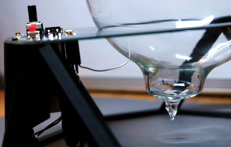
There’s a new hotness in plasma physics demos. With a sealed vessel of near-vacuum xenon and exactly the right kind of magnetic induction driver, you can conjure a shimmering toroidal halo of stable plasma. 

Producing the toroid effect requires high-voltage, high-frequency electronics. Compared to a typical Tesla coil the voltages are a bit lower at 600–1,000 volts, but the operating frequency is much higher at around 10–15 megahertz (MHz).

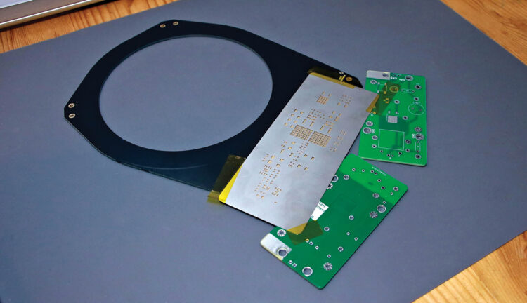
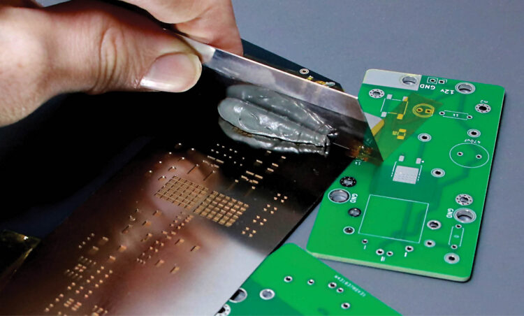
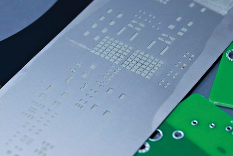
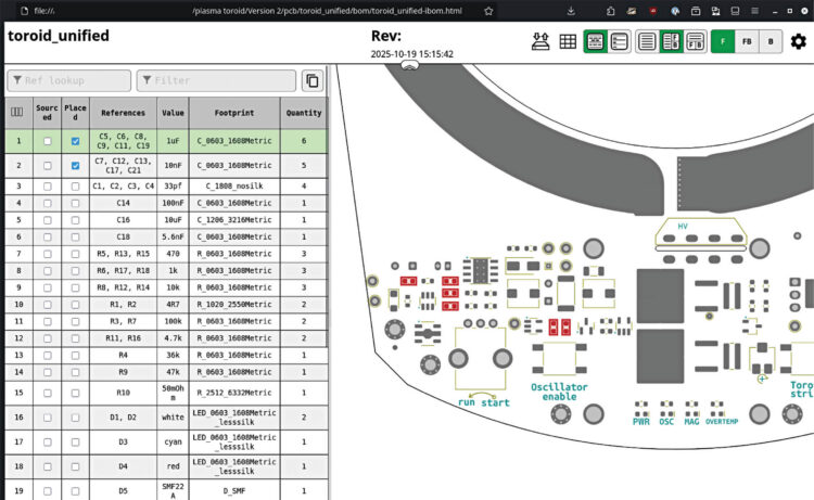
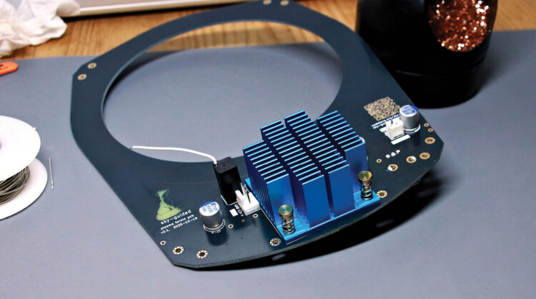
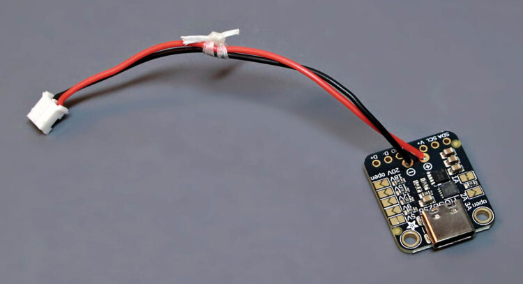
This fully-open-source design is intended to be as reproducible as possible. I’ve taken a “design for manufacturability” approach, using modern surface-mount components and building functionality into the printed circuit board itself.

Blazing Bagels

What is an inductively coupled plasma toroid?

YouTube player

Creating the xenon plasma toroid effect requires an intense and rapidly-oscillating magnetic field.

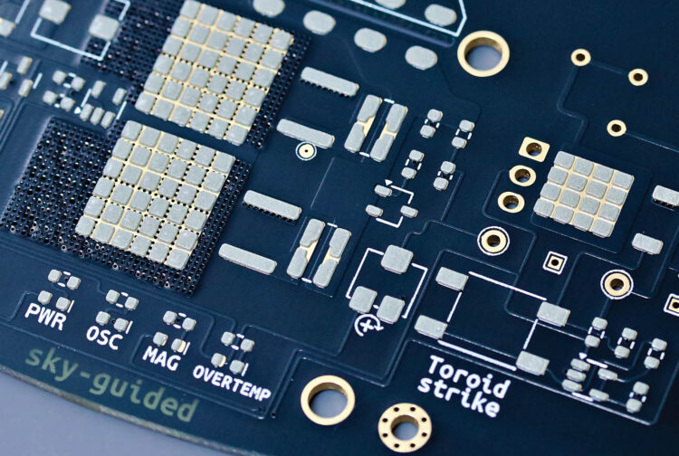
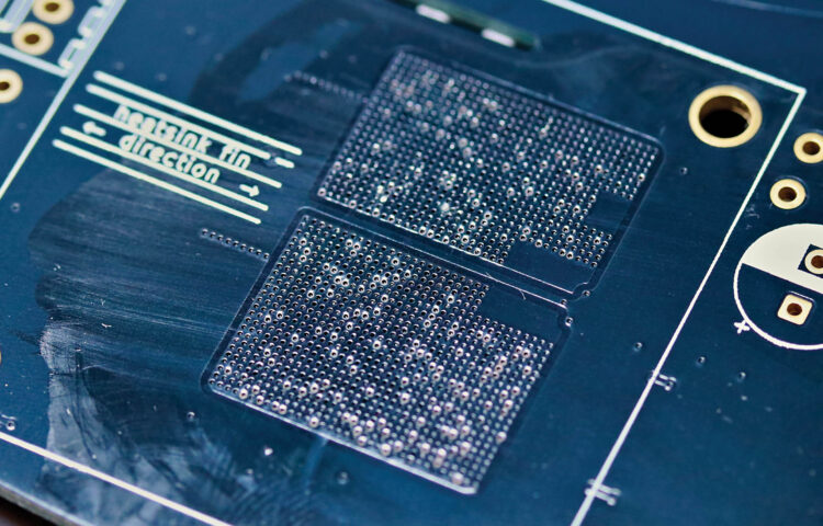
Our PCB is hiding a two-turn induction coil wrapped around the globe’s circumference. Rather than being made from wound wires, this coil is etched into the front and back copper layers of the board itself. This coil is driven by high-voltage alternating current at a frequency of about 12MHz.

Photography by sky-guided

Electrical current flowing through the coil creates a magnetic field through the coil’s center. Since the coil is being driven with AC, the orientation of this field is constantly flipping back and forth, 12 million times per second, indicated by the green arrows.

Due to a principle called Faraday’s law of induction, a changing magnetic field exerts forces on charged particles. So if we imagine placing a copper loop inside the coil, this force would be exerted on mobile electrons within the copper. The electrons would be driven in a circle, changing directions back and forth each time the magnetic field’s direction changes. This is an AC electrical current! It’s the working principle behind every electrical transformer.

Of course, in this device we don’t have any metal inside the glass globe. Instead we have plasma — and plasma is also electrically conductive.

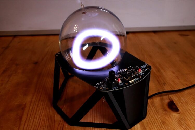
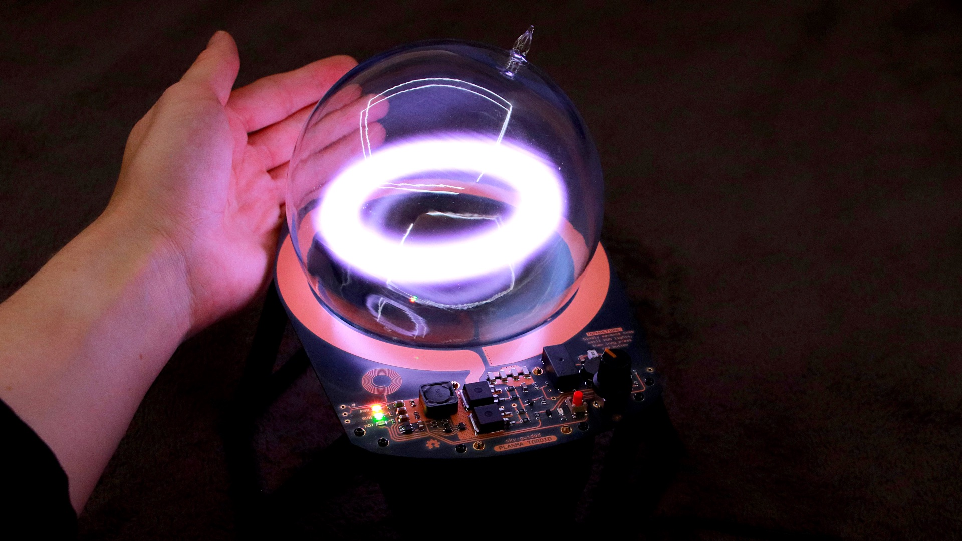
Inside the globe, low-pressure xenon gas is ionized to form a conductive loop of plasma. The driving magnetic coil is constantly pumping energy into this loop, allowing it to stay ionized and exist in a steady state.

We see a brightly glowing ring of xenon plasma. This plasma toroid slowly drifts and undulates, floating in convection currents within the low-pressure gas. It’s mesmerizingly beautiful.

Understanding the Electronics

High Voltage/High Frequency Oscillator

The primary drive coil is doing double duty. In addition to creating the magnetic fields necessary to form the plasma toroid, it’s also functionally integral to the self-oscillating resonant high-frequency/high-voltage generator.

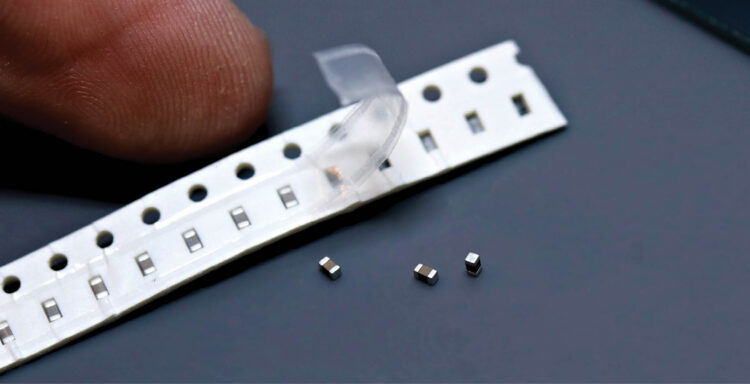
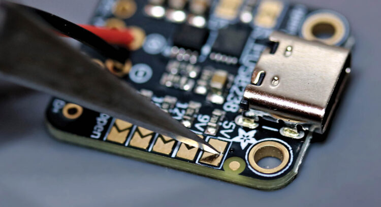
The primary drive coil acts as an electrical inductor. Looping back through its own magnetic field allows the field to usefully store energy. At one end of the drive coil is an array of four small ceramic chip capacitors.

These capacitors also store energy. However, there’s a subtlety: with AC electrical currents, capacitors and inductors each gain and lose energy 90 degrees out of phase with each other. As a result, energy will continually slosh back and forth between the capacitor’s internal electric fields and the inductor’s external magnetic fields. This behavior is almost perfectly analogous to a physical mass bouncing up and down on a spring.

Tank Circuit Resonant Oscillations

This arrangement of primary inductor and capacitor (marked Cp in the simplified schematic) in series forms what’s called a resonant tank circuit. Just like any other harmonic oscillator, feeding a tank circuit at exactly its natural resonant frequency steadily builds up the total energy in the system — exactly what we need to generate high voltages for the toroid.

Toroid Driver (simplified)

Feeding the resonant tank is done by rapidly switching a MOSFET on and off. Each time this transistor switches off, current flowing through the feeder inductor is diverted away from its natural path to ground and instead into the resonant tank.

Switch timing is done with an analog feedback network. Capacitors Cp and Cg are arranged together to create a capacitive voltage divider. This voltage divider converts the tank’s high-voltage AC oscillations into a lower-voltage AC signal to drive the MOSFET’s control pin. This AC drive signal is combined with a DC bias voltage (V_bias), shifting this drive signal a few volts upward to turn the MOSFET on for half of every cycle.

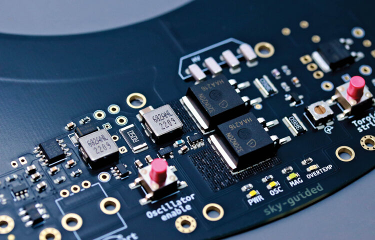
The actual circuit needs to be more complex than the simplified version. Handling real-world power levels requires four parallel capacitors and two MOSFETs. There are also small gate resistors to add switching phase delay, and a TVS protection diode to deflect any overvoltages away from the sensitive MOSFETs. A trim potentiometer allows adjustable control over bias voltage

Toroid Driver

Accessory Subcircuits

For this integrated PCB I’ve added some quality-of-life features. (You can see all these schematics and more at the Codeberg repo.)

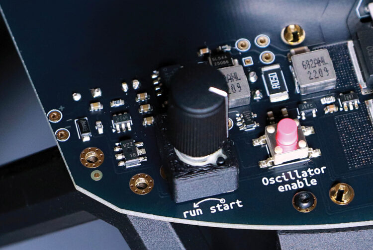
Oscillator Enable Toggler

Enable Toggler

It’s nice to have pushbutton on/off functionality. These kinds of self-latching circuits are common, and there are many ways of designing them.

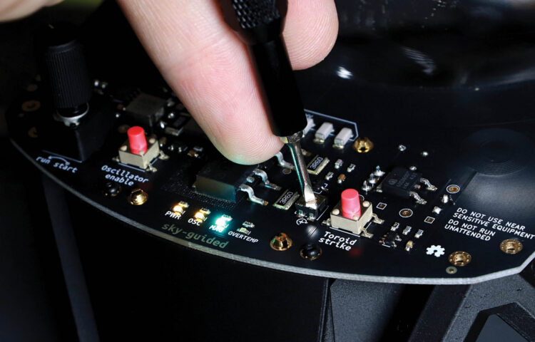
Magnetic Field Activity Indicator

Once enabled, how do we know the core driver is actually producing a useful magnetic field? The simplest way to monitor field activity is to put an isolated “pickup” coil near the main drive coil. Wireless power transfer from the main to the pickup coil easily illuminates an indicator LED.

Adjustable Current Limit

Driving the plasma with less power creates different effects — there’s a fun progression from a rotating churn to a perfectly still and stable halo as power is decreased. Power throttling also reduces waste heat.

Adjustable Current Limit

The left-hand side of this subcircuit is a buck converter, a very efficient way of reducing input power. (see Great Scott’s explanation below). Folks at Texas Instruments are cleverer than I am, so I’m letting their monolithic Simple Switcher chip do the heavy lifting.

YouTube player

The right-hand side of the subcircuit measures the toroid’s actual current draw. It creates a signal voltage that’s used as feedback so the buck converter knows how much limitation is necessary. Potentiometer RV1 acts as the adjustment knob.

Overheat Sensor

When a TMP708 integrated circuit exceeds 75°C (about 167°F), it lights up an indicator LED. This chip is located near the drive MOSFETs to provide a warning if they’re being pushed too hard.

Pushbutton Arc Start

Simply turning the core driver on isn’t enough to generate plasma. Similar to how hot water won’t boil without trace impurities, the xenon needs a tiny bit of seed ionization for the driver’s magnetic fields to act upon. If a few kilovolts are applied to the surface of the glass globe, that intense electric field can produce the seed ionization necessary to kick-start the toroid.

Arc Start

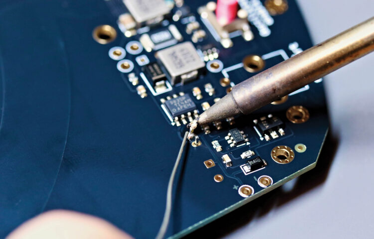
My arc start subcircuit creates high voltage pulses using a flyback converter. The mini flyback transformer (T1) I’m using was, ironically, designed for triggering xenon flash lamps.

Project Steps

1. Getting the Parts

1a. Xenon globe

The plasma toroid phenomenon requires a glass globe filled with low-pressure xenon.

The circuit presented here is designed for 1L, 13cm globes with a fill pressure of about 15 torr. Higher fill pressures (30+ torr) produce sharper, livelier toroids, but require greater drive power than our circuit was designed for; using them is not fully tested but may be possible with higher input voltages.

My globe was crafted by Massachusetts-based plasma artist Wayne Strattman.

“BagelFlask” xenon globes are sold by the Russia-based Zerg Labs. In addition to pure xenon, they also sell globes spiked with powdered metals which produce spectacular color effects. However, most of their globes are filled to the 30+ torr pressure range.

A few globes have shown up on AliExpress — try searching for “xenon plasma toroid ring tesla lamp.” Unfortunately most AliExpress listings are lacking in technical specifications.

1b. Circuit board — DIY

The raw printed circuit board can be ordered from just about any PCB manufacturer. Upload the project’s latest toroid_fab .zip file, from the Codeberg repo folder /pcb/toroid_unified/fabrication, to your board house of choice, and use the parameters recommended in /docs/pcb_parameters.txt. Make sure to include a solder stencil in the order.

The circuit requires about 50 individual components. You can find the entire list in /bom/toroid_unified_bom.csv.

1c. Circuit board — pre-assembled

If you’d prefer a pre-assembled circuit board with no need to solder components yourself, I’m offering a limited production run for sale on Tindie. You’ll still need to acquire your own xenon globe, print some structural parts, and do final system assembly.

2. PCB Assembly

Assembling the circuit board is done in four steps: applying solder paste using a solder stencil, placing surface-mount components, reflow soldering with a hotplate or oven, and finally hand-soldering through-hole components.

2a. Apply solder paste

Using a solder paste stencil makes it easy to reflow-solder an entire board at once. The stencil itself is laser-cut from very thin metal.

Good results require the stencil to lie as flat as possible against the PCB. To prevent the stencil from flexing over the edges of the board, use same-thickness bare PCBs as shims. The green ones shown I had left over from prototyping, but you’ll have material available regardless because PCBs are fabricated and shipped in batches of 3 to 5 or more.

Carefully align the stencil on the PCB, then secure it with Kapton tape. Apertures in the stencil should align perfectly with the board’s plated pads.

Spread a generous glob of well-mixed solder paste at one edge of the stencil. Using a thin, stiff squeegee, swipe the solder paste across apertures in the stencil. Hold the squeegee at about a 45° angle. The goal is to swipe the solder across the surface of the stencil, not jam it downward into the holes. I use a purpose-made steel squeegee tool, but something like a putty knife or an old credit card also works great.

Try to complete the application in a single pass, or two at most. If you completely mess up, clean the board and try again. Scrape leftover paste back into the jar.

Carefully lift away the stencil. You should see small amounts of grey solder paste sitting cleanly and neatly atop each pad. The applied paste has a working lifespan of several hours before it dries up.

2b. Place surface mount components

This board was designed to use 0603-size surface mount components. By modern electronics standards 0603 is medium-sized; by any normal human standard it’s miniscule. You’ll need sharp tweezers, good lighting, and either young eyes or a little magnification. Nonetheless, if you have a reasonably steady hand, then assembly is easier than you might think.

You can find the location of each component in the interactive bill of materials (IBOM) file ibom.html, located inside the /bom subfolder. Open the IBOM file in a web browser. If you bring a laptop to your work area then you can see the exact location of each component highlighted on mouseover. Otherwise, turn on the “fab” layer under the gear menu icon and make a print copy.

The IBOM is arranged by component type and roughly in order of smallest to largest, which is a good assembly sequence. Check off components as you place them.

Use tweezers to place each component. The parts can be dropped gently onto the solder pads and given a teeny tap to stick to the paste. You don’t need to squish or smear the solder. It’s OK if components are a bit crooked, because surface tension of the melting solder will pull everything into perfect alignment.

Pay careful attention to the orientation of diodes and integrated circuits. ICs will usually have a tiny dot to mark pin 1, which corresponds to an arrow on the PCB’s silkscreen paint. Diodes have a small line on the cathode. LEDs vary; some have the cathode marked in green, some only have glyphs on the underside, and some have subtle distinctions in electrode shape. Check the component datasheets if you’re unsure.

Once all the surface mount components are placed, you’re ready to reflow the board.

2c. Reflow soldering

I’m using a soldering hotplate for my PCB solder reflow. A reflow oven would work great too. Some folks go as low-tech as a kitchen skillet!

Your solder paste will recommend a reflow profile: holding and ramping between particular temperatures at particular rates. In practice the exact parameters are pretty forgiving. I’ve had great results from programming the hotplate to the max temperature recommended by the solder manufacturer, then placing the board on the cold hotplate and letting the plate warm up to full temperature at its own pace.

As the board heats up, the solder paste will start to sizzle and smoke. Don’t breathe this. Near the peak temperature, the solder joints will melt and turn to shiny liquid. The solder on the bigger components, and near the periphery of the board, will probably be the last to melt.

Once you’re sure everything has melted, use your tweezers to lift the board straight off the hotplate — don’t immediately tilt it or components will slide off. Set the board aside to cool.

2d. Inspect

Before moving on, examine the board thoroughly. Watch out for solder bridges and pins that didn’t fully reflow. Pluck away any balls of excess solder.

Leaked solder.

A tiny amount of solder and flux residue may have leaked through to the underside of the board below the MOSFETs, through the thermal conduction grid of tiny plated holes. You’ll especially need to remove any excess solder in this area or it could cause destructive shorts to the heatsink. Wipe away flux residue with isopropyl alcohol (aka isopropanol).

2e. Hand-solder through-hole parts

Hand-solder the remaining through-hole components. Start with the underside components, again working smallest to largest. Do the top-side potentiometer last, then trim its legs flush with the board’s underside.

3. System Assembly

3a. Attach the heatsink

Mount the heatsink to the underside of the PCB using the four spring-loaded pushpins. A heatsink is mandatory for even short test runs. The board is marked with the correct fin orientation.

3b. Prep the USB board

The Adafruit USB-PD power supply board needs a small adjustment before installation. In order to get full power, you need to cut through the selectable jumper trace labeled “5V” as shown.

Now solder a 2-pin JST-PH connector to the USB-PD module. (Be careful if you use a pre-made connector, because JST polarity is not standardized.) Bundle the power leads with a small zip tie, or with cable lacing, otherwise they’ll pick up interference from the driver coil.

3c. Mount boards and fan

The support structure is 3D printed; you’ll find the toroid_support_singleprint.step file for printing in the /mechanical folder. Matte black PLA works nicely.

Tenderly screw everything together using M2 thread-forming screws. Any screw length from 4mm–6mm is fine.

The fan gets attached to the scaffold underneath, using standard PC case fan screws. Don’t overtighten these, since the plastic is easy to split. Make sure the fan is oriented to blow upward into the heatsink. The USB-PD module can be attached in either a left- or right-facing orientation.

Screw the PCB to the top of the support structure, then attach the fan and power connectors. Fans with three- and four-pin connectors both fit on the three-pin fan header.

3d. Mount the knob

Snap the printed knob shroud over the potentiometer. This is optional but makes the finished device look a bit nicer.

Press-fit the potentiometer knob. Orient the knob’s marking so that it’s at about the 1:30 position at full clockwise rotation, and about 4:30 at full counterclockwise.

3e. Add the xenon globe

Finally, place your xenon globe in the center of the coil. Bend the transformer’s white output wire so that the uninsulated tip touches the globe’s surface. Keep this wire at least a centimeter or two away from the circuit board. You may need to experiment with exact placement for best results.

Conclusion

Time to Make the Donuts!

Initialization

The very first time you start, begin by turning both the current control knob (marked “run/start”) and the drive bias trimmer potentiometer (marked with a circular arrow and plus sign) to their full counterclockwise positions. Then plug in USB-C power from a wall adapter.

The power LED (“PWR”) should come on, and you should be able to turn on/off the oscillator enable indicator LED (“OSC”) with a press of the “Oscillator enable” button. The underside cooling fan should spin. The LEDs for “MAG” and “OVERTEMP” should remain off.

Raise the control knob to about 75% of maximum, and turn on the Oscillator enable. Using a small screwdriver, very slowly increase the bias trim potentiometer until the MAG LED illuminates. This indicates that the circuit is in oscillation. You should only have to set this trimmer potentiometer once.

Now when you press the Oscillator enable button, both the OSC and MAG LEDs should turn on together.

Operation

Turn the control knob to maximum and enable the oscillator. The MAG LED should illuminate brightly. Now tap the “Toroid strike” button until you see plasma. If this doesn’t work, try briskly twisting the glass globe back and forth a bit. If it takes more than 20 seconds to get plasma after MAG illuminates, turn off the Oscillator enable and give the board 30 seconds to cool down.

Once a toroid forms, slowly reduce the control knob to your desired intensity. Running at maximum may lead to overheating. If the OVERTEMP led lights up, turn OSC off and let the board cool.

Playing with Plasma

The ring of plasma can wriggle and writhe like a living creature! Try different power levels to see how the ionized xenon behaves. For added fun you can make the toroid swirl with a twist of the globe, or even lift it up a few centimeters with plasma still inside (if it’s not too warm yet). Bringing a strong magnet near the globe may cause the toroid to flex and curl.

The plasma toroid phenomenon was practically unknown to makers until just a few years ago. If you have ideas for how you’d build an even better circuit, give it a shot!


CAUTION: This plasma toroid generator is an experimental device which creates high-voltage radio frequency energy. It will cause electromagnetic interference against nearby devices. Capacitive touchscreens and touch buttons seem the most susceptible. I’ve seen electronics register spurious touch-button input from 2 meters away, and one friend had their phone touchscreen stop responding for several minutes.

Absolutely do not run the toroid near safety-critical electronics. This includes anyone with hearing aids, an insulin pump, or pacemaker.

Do not touch the primary drive coil — if you do, you can get high-voltage RF burns. Some parts of the coil are energetic enough to zap you even through the PCB’s solder mask without touching bare metal.

The drive MOSFETs and xenon globe get hot during normal operation — 60°C–80°C (140°F–180°F) is normal.


This project appeared in Make: Volume 96.