radar speed detector opener

I was browsing through a department store one day, in search of a gift for my 8-year-old daughter, when I came across Mattel’s Hot Wheels Radar Gun ($30). The box said that this toy could clock the speeds of not only miniature Hot Wheels cars, but also full-sized vehicles.

I figured the toy must have severe limitations, but decided to buy one for my daughter anyway. It turns out that she (we) loved it, and we found that it could accurately measure the speeds of toy cars, cars on the road, even joggers. To my amazement, the detector even measured the speeds of spinning objects like bicycle wheels.

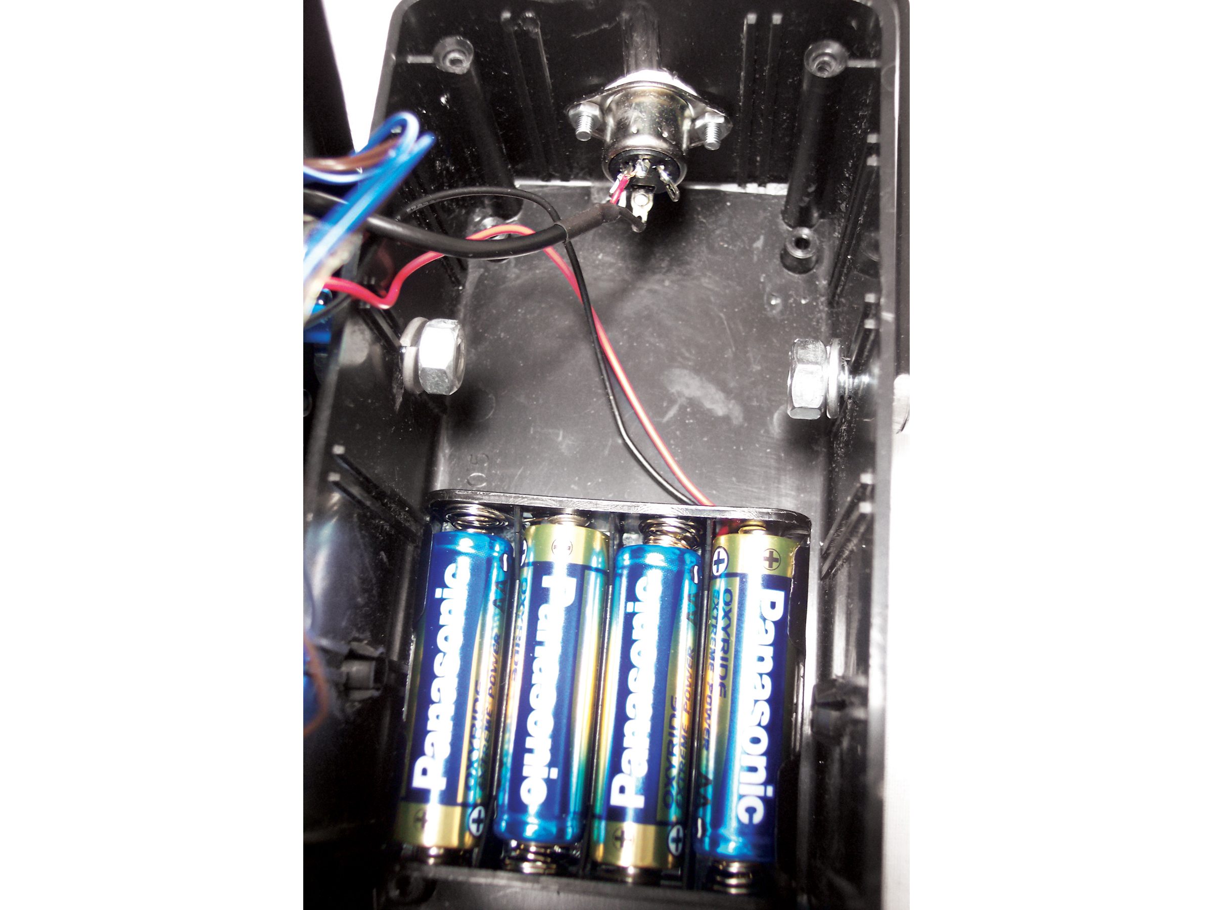
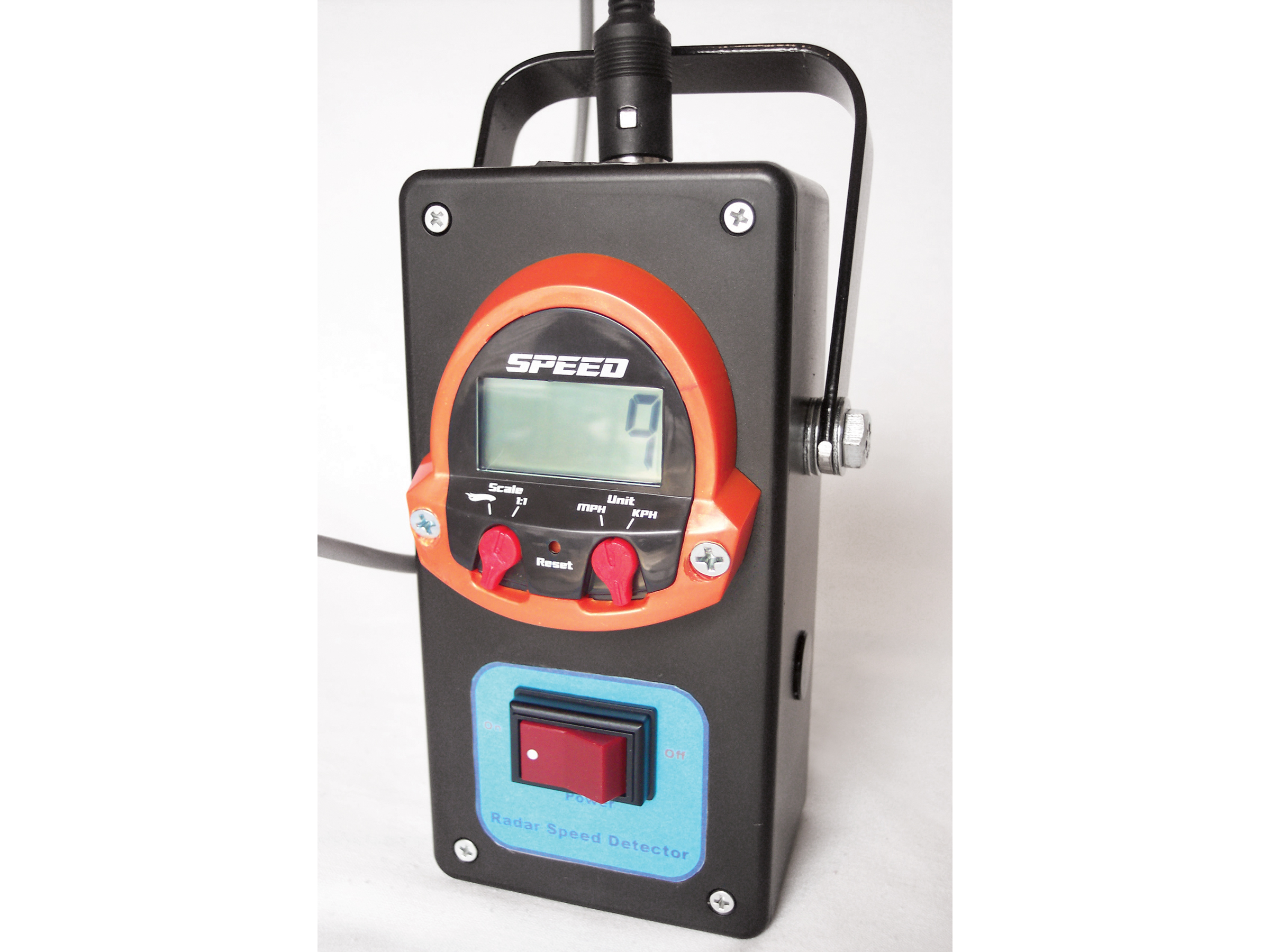
Operating the toy is simple: you aim the gun, squeeze the trigger, and then read the detected speed on the LCD in back. Hold the trigger down for a while and then release, and you’ll get the maximum speed detected during that time. A switch selects either mph or kph readings, and another switch toggles the display units between 1:64 scale (for Hot Wheels) and 1:1 scale actual speeds. Power comes from 4 AAA batteries housed in the handle.

Inside, the Mattel gun uses Doppler radar, just like the expensive speed detection systems used by law enforcement. It transmits a continuous wave at 10.525GHz, then measures the frequency that returns after the wave bounces off a moving target. The main functional difference between the Mattel toy and a $1,000-plus pro model is detection range, which for the toy maxes out at 40 feet. I suspect that this keeps the microwave emissions low enough to guarantee child safety.

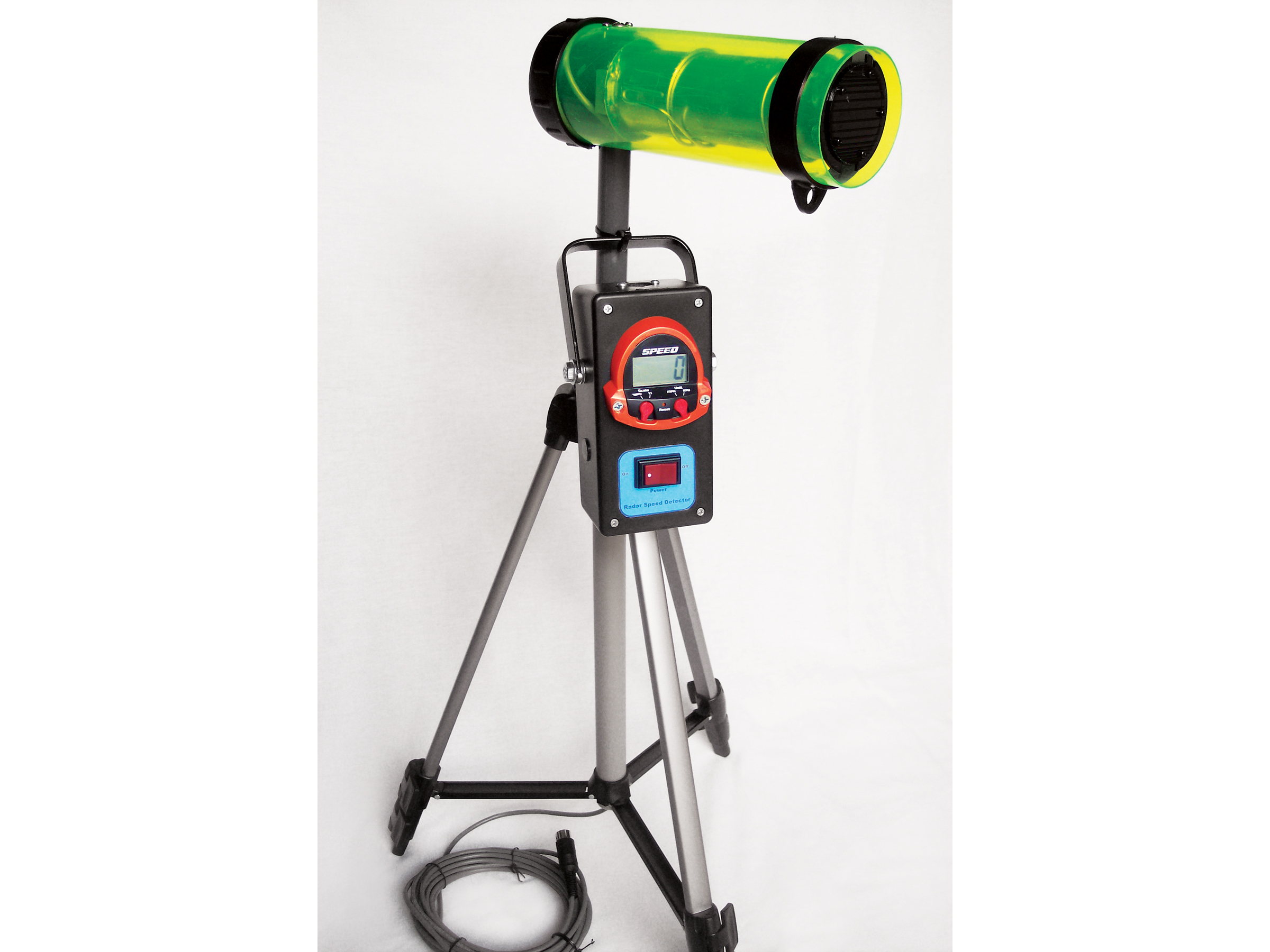
Limitations aside, I realized that this so-called toy offers some interesting prospects. The wheels in my mind began to churn, and I decided to purchase another unit for my own use. I disassembled the gun and decided to repackage it to appear more professional — looks really are everything.

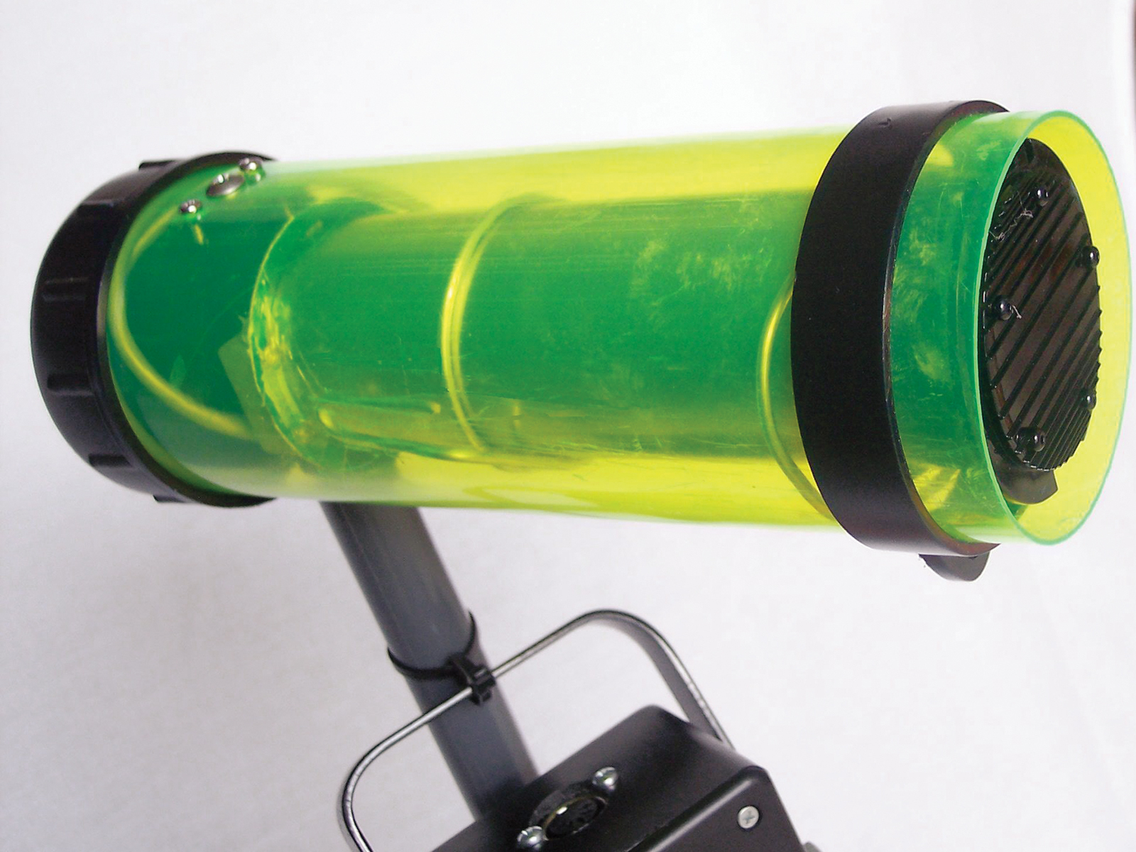
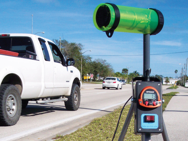
I separated the detector component itself (the waveguide antenna) from the display and control panel, then connected the two with a length of instrumentation cable. This configuration lets you position the antenna close to traffic on a tripod, and operate it remotely from a safe distance.

Project Steps

Disassemble the toy.

Disassembly is no easy task, as there are 12 screws, each concealed with plastic inserts. I used a drill and ¼” bit to carefully drill out the inserts and gain access to the screws. Use extreme caution with the drill, since some of the screws are located very close to sensitive internal components.

After removing all the screws and opening the case, you’ll see the long, cylindrical waveguide antenna and a small circuit board that carries the buttons and LCD panel. (The waveguide is a hollow tube that surrounds the microwave antenna and directs and concentrates its signal.)

After recording their locations so you can reattach them correctly later, unsolder all the wires that connect the waveguide, battery compartment, and trigger switch. Be careful when working with the waveguide, which is made of a thin, dielectric material and dents easily. After detaching all the wires, remove the waveguide and display panel, and set them aside.

Part I - Upgrade the antenna housing.

For the waveguide antenna housing, I chose an “Ice Tube” by Alvin. I’ve used these 3″ diameter acrylic document tubes in previous projects, and I like them. First and foremost, they look cool and futuristic — transparent with various tints. They’re also fairly rigid and you can easily cut them with a hacksaw. I used transparent green tubing and cut an 8¾” length.

For a post that holds up the housing and makes it attachable to a tripod, use a ¾” diameter threaded PVC nipple, 8″ in length. Drill a ¾” hole in one end of the acrylic tube and insert the nipple through it. Then screw a shrub sprinkler head onto the end of the nipple. Just below the sprinkler head, drill a ¼” exit hole to route the cable through.

Secure the sprinkler head to the wall of the tube opposite the hole, using the screw that came with the sprinkler head plus 2 smaller screws on either side to prevent rotation. For these, drill 3/32″ holes through the tube and head, and apply two 1″×¼” sheet metal screws.

To secure the waveguide centered inside the tube, use 12-gauge steel wire, carefully wrapped around the waveguide in a spring-like fashion to form 2 mounts, one at each end. Pressure and friction on this wire are what holds the waveguide in the tube housing. There are no screw attachments.

Part II - Upgrade the antenna housing.

Before inserting the waveguide with mounts into the housing, solder on a new, longer interface cable that will support remote operation. The toy originally used a 4″ length of shielded 2-conductor cable, so I figured that the new cable should also be shielded.

In my garage, I found a 20′ length of instrumentation cable with shielding. Cut and strip one end of the cable, and solder 2 of the available 4 signal wires to the signal contacts on the antenna’s round printed circuit board. Also solder the uninsulated drain wire, which connects to the shielding, to the board’s ground contact in the middle.

Route the opposite end of the cable through the waveguide housing and PVC nipple, and then carefully push the waveguide assembly into the housing. To attach the housing to a camera tripod, remove the tripod’s head assembly and support tube from the base, then route the antenna cabling through the hole, and slide in the PVC nipple and waveguide housing.

The other end of the cable would attach to the display, but I wanted to make it easily detachable for transport. So I obtained a 5-pin DIN male connector plug and matching jack. Solder the 3 conductors that were connected at the other end to 3 contacts on the DIN plug.

Part I - Build the display housing.

To house the radar detector’s display and controls, originally on the back of the toy gun, I used a 6″×3″×2″ project case. First I made a carrying handle out of a bar of 0.1″ thick steel (aluminum would have been easier to work with).

Drill ¼” holes in each end of the steel and bend it into a U shape. Drill corresponding holes in the display housing and attach the handle using hex bolts, nuts, and washers. One of the nice things about the handle is that it also functions as a stand, allowing hands-free viewing when the display unit is on a tabletop or other flat surface.

I needed to make a large hole in the lid of the display housing to fit the LCD display panel. Since I didn’t have any large-diameter bits, I used a ¼” bit to make a series of small perforations in the plastic. Punch out the section with diagonal cutters, and file the edges smooth. Then install the LCD panel to the lid by running a couple of 1/8″×¾” sheet metal screws through its 2 original mounting holes.

To replace the functionality of the original momentary trigger switch, I chose a double-pole, double-throw rocker switch. This has the advantage of allowing for automatic, hands-free speed measurements. To install the switch, drill a ¾” hole into the display housing lid, centered below the display, and secure the switch in place with its retaining nut. To reinforce the display and switch, you might also add some glue.

Part II - Build the display housing.

On the top of the display housing, install the female DIN connector receptacle, for plugging in the cable. Drill a ¾” hole into the top of the display housing and attach the jack on the inside using a pair of 3mm×8mm screws and nuts.

The original radar gun used 4 AAA batteries. This would be fine for our new configuration, but since there is plenty of room inside the display housing, I decided to go with AAs, which have twice the capacity of their AAA cousins.

A quick measurement with my multimeter revealed that the radar system draws about 24mA from the batteries connected in series. This translates to almost 100 hours of continuous use with AA alkalines (assuming 2200mAh each). Install a 4-AA battery holder inside the display housing using double-stick mounting tape.

Solder all the connections.

With all the hardware installed inside the display housing, it’s time to solder all the connections. The wires connect to 3 components: power switch, batteries, and the DIN connector for the antenna. For the DIN jack, the toy’s original 4″ antenna cable had 3 wires, red, white, and a shielding conductor covered with black heatshrink. Solder these 3 wires to the connector contacts matching the other end of the cable, using a multimeter to make sure you get the correspondence right.

The toy’s power switch wiring consists of 4 individual wires: 2 brown and 2 blue. Position and solder these to the DPDT switch, following the same pattern as the original manual trigger switch.

Finally, the toy’s battery wiring consists of 2 individual wires, red and black. Solder these directly to the corresponding contacts on the battery holder. That’s it for the wiring. After closing up the case and plugging in the antenna cable, you’re ready to go.

Let the fun begin!

I started out by having a family member walk in front of the antenna unit. At a normal pace, the display registered 2 mph, and a more brisk pace yielded a reading of 4–5 mph.

Next, I decided to try measuring the speed of a spinning bicycle wheel. The tripod was handy for this test, since it let me focus the waveguide precisely where I wanted. I placed the bicycle upside down on the floor, supported by its handlebars and seat. Then I turned the pedal to get the rear wheel spinning, and I clocked it at a maximum rate of 15 mph. So far, so good.

Then it was time for the real test, with actual cars on the road. I took the unit outside near the street and set up the tripod. It wasn’t long before a vehicle came along, and the readout showed 19 mph. That was great — the detector was showing a speed for a passing automobile. But I wondered about its accuracy, so I decided to get into my car and drive down my street past the detector myself. Watching my speedometer, I drove at a steady speed of 21 mph. Heading back to my driveway, I was anxious to see what the device had measured, and to my delight the reading was 21 mph!

I’ve done several projects over the years, and this one has been one of the most satisfying. The Hot Wheels Radar Gun has some great hardware inside, and for my minimal investment, I now have a system that provides a useful function that I’m sure I’ll be using and enjoying quite a bit for years to come.

Conclusion

This project first appeared in MAKE Volume 10, page 148.