Make: Electronics is an electronics primer for the early 21st century. It’s written for the absolute beginner and all those who’ve wanted to learn electronics. Those who’ve wanted to build all the cool kits out there, or to try their hand at programming microcontrollers, but who’ve found themselves intimidated by existing books and online resources that seem to be written by deep geeks for deep geeks.

Make: Electronics is written in a fun, clear-spoken, graphical style. It includes 36 experiments and projects, plus dozens of sidebars on the science, history, and personalities behind electronics. And it’s brimming with hundreds of photos, illustrations, diagrams, schematics, even cartoons, all done by Charles Platt!

It was Platt’s beginner electronics guide and 555 timer projects in MAKE Volume 10 that made us realize he might be the man to pull off the book we desired. So it’s fitting that we’ve chosen this new 555 timer project to present here.

It occurs midway through the book, as Experiment 18, so it’s a bit advanced for the beginner (don’t worry, the book starts off with very easy fare), but if you follow the instructions carefully, you’ll be fine. And one of the core lessons of the book is to not be afraid of failure, so if it takes you a few tries, that’s fine too.

Be patient and learn from your mistakes. (If you’re new to electronics you might want to read Platt’s “Your Electronics Workbench” and do the projects in “The Biggest Little Chip,” both in Volume 10, before tackling this project.)

We hope you enjoy this peek at Make: Electronics, and pick up a copy for yourself, a friend, or a family member. They’re probably tired of seeing you having all the geeky fun, but are too embarrassed to let you in on their ignorance. We know they’re out there.

When we announced the book on Make: Online, we started getting “confessional” posts from readers. One wrote: “Prepare yourselves. You’re going to sell one BILLION of these books. This is exactly what I’ve been looking for, for over a decade.” Thanks. We made this book for you. (And we’ll settle for a million.)

—Gareth Branwyn

What will the next generation of Make: look like? We’re inviting you to shape the future by investing in Make:. By becoming an investor, you help decide what’s next. The future of Make: is in your hands. Learn More.

Project Steps

Display.

Because the 555 timer chip can easily run at thousands of cycles per second, we can use it to measure human reactions. You can compete with friends to see who has the fastest response — and note how your response changes depending on your mood, the time of day, or how much sleep you got last night.

Before going any further, I have to warn you that this circuit requires a lot of wiring, and will only just fit on a breadboard that has 63 rows of holes. Still, we can build it in a series of phases, which should help you to detect any wiring errors as you go.

You can use three separate LED numerals for this project, but I suggest that you buy the Kingbright BC56-11EWA, which contains three numerals in one big package.

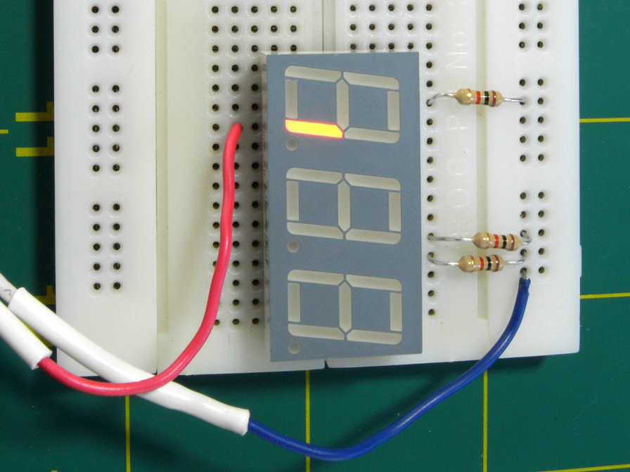
You should be able to plug it into your breadboard, straddling the center channel. Put it all the way down at the bottom of the breadboard, as shown in the step photo. Don’t put any other components on the breadboard yet.

Now set your power supply to 9 volts (or use a 9-volt battery), and apply the negative side of it to the row of holes running up the breadboard on the right-hand side. Insert a 1K resistor between that negative supply and each of pins 18, 19, and 26 of the Kingbright display, which are the “common cathode,” meaning the negative connection shared by each set of LED segments in the display.

The pin numbers of the chip are shown in the first step photo. If you’re using another model of display, you’ll have to consult a data sheet to find which pin(s) are designed to receive negative voltage.

Switch on the power supply and touch the free end of the positive wire to each row of holes serving the display on its left and right sides. You should see each segment light up, as shown in the photo in Step 1.

Each numeral from 0 to 9 is represented by a group of these segments. The segments are always identified with lowercase letters a through g, as shown in the second step photo. In addition, there is often a decimal point, and although we won’t be using it, I’ve identified it with the letter h.

Check the first step photo showing the Kingbright display, and you’ll see I have annotated each pin with its function. You can step down the display with the positive wire from your power supply, making sure that each pin lights an appropriate segment.

Incidentally, this display has two pins, numbered 3 and 26, both labeled to receive negative voltage for the first of the digits.

Why two pins instead of one? I don’t know. You need to use only one, and as this is a passive chip, it doesn’t matter if you leave the unused one unconnected. Just take care not to apply positive voltage to it, which would create a short circuit.

A numeric display has no power or intelligence of its own. It’s just a bunch of light-emitting diodes. It’s not much use, really, until we can figure out a way to illuminate the LEDs in appropriate groups — which will be the next step.

Counting.

Fortunately, we have a chip known as the 4026, which receives pulses, counts them, and creates an output designed to work with a seven-segment display so that it shows numbers 0–9. The only problem is that the 4026 is a rather old-fashioned CMOS chip (meaning, Complementary Metal Oxide Semiconductor) and is thus sensitive to static electricity.

Switch off your power supply and connect its wires to the top of the breadboard, noting that for this experiment, we’re going to need positive and negative power on both sides. See the photo for details. If your breadboard doesn’t already have the columns of holes color-coded, I suggest you use Sharpie markers to identify them, to avoid polarity errors that can fry your components.

New line.The 4026 counter chip is barely powerful enough to drive the LEDs in our display when powered by 9 volts. Make sure you have the chip the right way up, and insert it into the breadboard immediately above your three-digit display, leaving just one row of holes between them empty.

The schematic in the first step photo shows how the pins of the 4026 chip should be connected. The arrows tell you which pins on the display should be connected with pins on the counter.

The second step photo shows the “pinouts” (i.e., the functions of each pin) of a 4026 counter chip. You should compare this with the schematic in the first step photo.

Include a tactile switch between the positive supply and pin 1 of the 4026 counter, with a 10K resistor to keep the input to the 4026 counter negative until the button is pressed. Make sure all your positives and negatives are correct, and turn on the power.

You should find that when you tap the tactile switch lightly, the counter advances the numeric display from 0 through 9 and then begins all over again from 0. You may also find that the chip sometimes misinterprets your button-presses, and counts two or even three digits at a time. I’ll deal with this problem a little later on.

The LED segments won’t be glowing very brightly, because the 1K series resistors deprive them of the power they would really like to receive. Those resistors are necessary to avoid overloading the outputs from the counter.

Assuming that you succeed in getting your counter to drive the numeric display, you’re ready to add two more counters, which will control the remaining two numerals. The first counter will count in ones, the second in tens, and the third in hundreds.

In the step photo, I’ve used arrows and numbers to tell you which pins of the counters should be connected to which pins of the numeric display. Otherwise, the schematic would be a confusing tangle of wires crossing each other.

At this point, you can give up in dismay at the number of connections — but really, using a breadboard, it shouldn’t take you more than half an hour to complete this phase of the project. I suggest you give it a try, because there’s something magical about seeing a display count from 000 through 999 “all by itself,” and I chose this project because it also has a lot of instructional value.

S1 is attached to the “clock disable” pin of IC1, so that when you hold down this button, it should stop that counter from counting. Because IC1 controls IC2, and IC2 controls IC3, if you freeze IC1, the other two will have to wait for it to resume. Therefore you won’t need to make use of their “clock disable” features.

S2 is connected to the “reset” pins of all three counters, so that when you hold down this button, it should set them all to zero.

S3 sends positive pulses manually to the “clock input” pin of the first counter.

S1, S2, and S3 are all wired in parallel with 1K resistors connected to the negative side of the power supply. The idea is that when the buttons are not being pressed, the “pull-down” resistors keep the pins near ground (zero) voltage. When you press one of the buttons, it connects positive voltage directly to the chip, and easily overwhelms the negative voltage. This way, the pins remain either in a definitely positive or definitely negative state.

If you disconnect one of these pull-down resistors you are likely to see the numeric display “flutter” erratically. (The numeric display chip has some unconnected pins, but this won’t cause any problem, because it is a passive chip that is just a collection of LED segments.)

Always connect input pins of a CMOS chip so that they are either positive or negative.

I suggest that you connect all the wires shown in the schematic first. Then cut lengths of 22-gauge wire to join the remaining pins of the sockets from IC1, IC2, and IC3 to IC4.

Switch on the power and press S2. You’ll see three zeros in your numeric display.

Each time you press S3, the count should advance by 1. If you press S2, the count should reset to three zeros. If you hold down S1 while you press S3 repeatedly, the counters should remain frozen, ignoring the pulses from S3.

Pulse generation.

A 555 timer is ideal for creating a stream of pulses that drive a counter chip. The image shows how to connect these chips to the positive and negative rails on your breadboard. Also I’m showing the connection between pins 2 and 6 in the way that you’re most likely to make it, via a wire that loops over the top of the chip.

For the current experiment, I’m suggesting initial component values that will generate only four pulses per second. Any faster than that, and you won’t be able to verify that your counters are counting properly.

Install IC5 and its associated components on your breadboard immediately above IC1. Don’t leave any gap between the chips. Disconnect S3 and R3 and connect a wire directly between pin 3 (output) of IC5 and pin 1 (clock) of IC1, the topmost counter.

Power up again, and you should see the digits advancing rapidly in a smooth, regular fashion. Press S1, and while you hold it, the count should freeze. Release S1 and the count will resume. Press S2 and the counter should reset, even if you are pressing S1 at the same time.

Refinements.

Now it’s time to remember that what we really want this circuit to do is test a person’s reflexes. When the user starts it, we want an initial delay, followed by a signal — probably an LED that comes on. The user responds to the signal by pressing a button as quickly as possible. During the time it takes for the person to respond, the counter will count milli-seconds. When the person presses the button, the counter will stop. The display then remains frozen indefinitely, displaying the number of pulses that were counted before the person was able to react.

How to arrange this? I think we need a flip-flop. When the flip-flop gets a signal, it starts the counter running — and keeps it running. When the flip-flop gets another signal (from the user pressing a button), it stops the counter running, and keeps it stopped.

How do we build this flip-flop? Believe it or not, we can use yet another 555 timer, in a new manner known as bistable mode.

In bistable mode, the 555 has turned into one big flip-flop. To avoid any uncertainty, we keep pins 2 and 4 normally positive via pull-up resistors, but negative pulses on those pins can overwhelm them when we want to flip the 555 into its opposite state.

The schematic for running a 555 timer in bistable mode, controlled by two pushbuttons, is shown in the first step photo. You can add this above your existing circuit. Because you’re going to attach the output from IC6 to pin 2 of IC1, the topmost counter, you can disconnect S1 and R1 from that pin. See second step photo.

Now, power up the circuit again. You should find that it counts in the same way as before, but when you press S4, it freezes. This is because your bistable 555 timer is sending its positive output to the “clock disable” pin on the counter. The counter is still receiving a stream of pulses from the astable 555 timer, but as long as pin 2 is positive on the counter, the counter simply ignores the pulses.

Now press S5, which flips your bistable 555 back to delivering a negative output, at which point the count resumes. We’re getting close to a final working circuit here. We can reset the count to zero (with S3), start the count (with S5), and wait for the user to stop the count (with S4). The only thing missing is a way to start the count unexpectedly.

The delay.

Suppose we set up yet another 555 in mono-stable mode. Trigger its pin 2 with a negative pulse, and the timer delivers a positive output that lasts for, say, 4 seconds. At the end of that time, its output goes back to being negative. Maybe we can hook that positive-to-negative transition to pin 4 of IC6. We can use this instead of switch S5, which you were pressing previously to start the count.

Check the final schematic to the left (repeated for your convenience), which adds another 555 timer, IC7 above IC6. When the output from IC7 goes from positive to negative, it will trigger the reset of IC6, flipping its output negative, which allows the count to begin. So IC7 has taken the place of the start switch, S4. You can get rid of S4, but keep the pull-up resistor, R9, so that the reset of IC6 remains positive the rest of the time.

This arrangement works because I have used a capacitor, C4, to connect the output of IC7 to the reset of IC6. The capacitor communicates the sudden change from positive to negative, but the rest of the time it blocks the steady voltage from IC7 so that it won’t interfere with IC6.

The final schematic shows the three 555 timers all linked together, as you should insert them above the topmost counter, IC1. I also added an LED to signal the user. The second picture is a photograph of my working model of the circuit.

Because this circuit is complicated, I’ll summarize the sequence of events when it’s working. Refer to the final schematic while following these steps:

User presses Start Delay button S4, which triggers IC7.

IC7 output goes high for a few seconds while C5 charges.

IC7 output drops back low.

IC7 communicates a pulse of low voltage through C4 to IC6, pin 4.

IC6 output flips to low and flops there.

Low output from IC6 sinks current through an LED and lights it.

Sequence of events cont’d:

Low output from IC6 also goes to pin 2 of IC1.

Low voltage on pin 2 of IC1 allows IC1 to start counting.

User presses S3, the “stop” button.

S3 connects pin 2 of IC6 to ground.

IC6 output flips to high and flops there.

High output from IC6 turns off the LED.

High output from IC6 also goes to pin 2 of IC1.

Sequence of events cont’d.

High voltage on pin 2 of IC1 stops it from counting.

After assessing the result, user presses S2.

S2 applies positive voltage to pin 15 of IC1, IC2, and IC3.

Positive voltage resets counters to zero.

The user can now try again.

Meanwhile, IC5 is running continuously.

In case you find a block diagram easier to understand, I’ve included that, too.

Use the reflex tester.

At this point, you should be able to fully test the circuit. When you first switch it on, it will start counting, which is slightly annoying, but easily fixed. Press S3 to stop the count. Press S2 to reset to zero.

Now press S4. Nothing seems to happen — but that’s the whole idea. The delay cycle has begun in stealth mode. After a few seconds, the delay cycle ends, and the LED lights up. Simultaneously, the count begins. As quickly as possible, the user presses S3 to stop the count. The numerals freeze, showing how much time elapsed.

There’s only one problem — the system hasn’t yet been calibrated. It’s still running in slow-motion mode. You need to change the resistor and capacitor attached to IC5 to make it generate 1,000 pulses per second instead of just three or four.

Substitute a 10K trimmer potentiometer for R8 and a 1μF capacitor for C2. This combination will generate about 690 pulses per second when the trimmer is presenting maximum resistance. When you turn the trimmer down to decrease its resistance, somewhere around its halfway mark the timer will be running at 1,000 pulses per second.

How will you know exactly where this point is? Ideally, you’d attach an oscilloscope probe to the output from IC5. But, most likely you don’t have an oscilloscope, so here are a couple other suggestions.

First remove the 1μF capacitor at C2 and substitute a 10μF capacitor. Because you are multiplying the capacitance by 10, you’ll reduce the speed by 10. The leftmost digit in your display should now count in seconds, reaching 9 and rolling over to 0 every 10 seconds. You can adjust your trimmer potentiometer while timing the display with a stopwatch. When you have it right, remove the 10μF capacitor and replace the 1μF capacitor at C2.

The only problem is, the values of capacitors may be off by as much as 10%. If you want to fine-tune your reflex timer, you can proceed as follows. Disconnect the wire from pin 5 of IC3, and substitute an LED with a 1K series resistor between pin 5 and ground. Pin 5 is the “carry” pin, which will emit a positive pulse whenever IC3 counts up to 9 and rolls over to start at 0 again. Because IC3 is counting tenths of a second, you want its carry output to occur once per second.

Now run the circuit for a full minute, using your stopwatch to see if the flashing LED drifts gradually faster or slower than once per second. If you have a camcorder that has a time display in its viewfinder, you can use that to observe the LED.

If the LED flashes too briefly to be easily visible, you can run a wire from pin 5 to another 555 timer that’s set up in monostable mode to create an output lasting for around 1/10 of a second. The output from that timer can drive an LED.

Conclusion

Enhancements

It goes without saying that anytime you finish a project, you see some opportunities to improve it. Here are some suggestions:

  1. No counting at power-up. It would be nice if the circuit begins in its “ready” state, rather than already counting. To achieve this you need to send a negative pulse to pin 2 of IC6, and maybe a positive pulse to pin 15 of IC1. Maybe an extra 555 timer could do this. I’m going to leave you to experiment with it.
  2. Audible feedback when pressing the Start button. Currently, there’s no confirmation that the Start button has done anything. All you need to do is buy a piezoelectric beeper and wire it between the right-hand side of the Start button and the positive side of the power supply.
  3. A random delay interval before the count begins. Making electronic components behave randomly is very difficult, but one way to do it would be to require the user to hold his finger on a couple of metal contacts. The skin resistance of the finger would substitute for R11. Because the finger pressure wouldn’t be exactly the same each time, the delay would vary. You’d have to adjust the value of C5.

Summing Up

This project demonstrated how a counter chip can be controlled, how counter chips can be chained together, and three different functions for 555 timers. It also showed you how chips can communicate with each other, and introduced you to the business of calibrating a circuit after you’ve finished building it.

Naturally, if you want to get some practical use from the circuit, you should build it into an enclosure with heavier-duty pushbuttons — especially the button that stops the count. You’ll find that when people’s reflexes are being tested, they are liable to hit the Stop button quite hard.

This project first appeared in MAKE Volume 21, page 96.