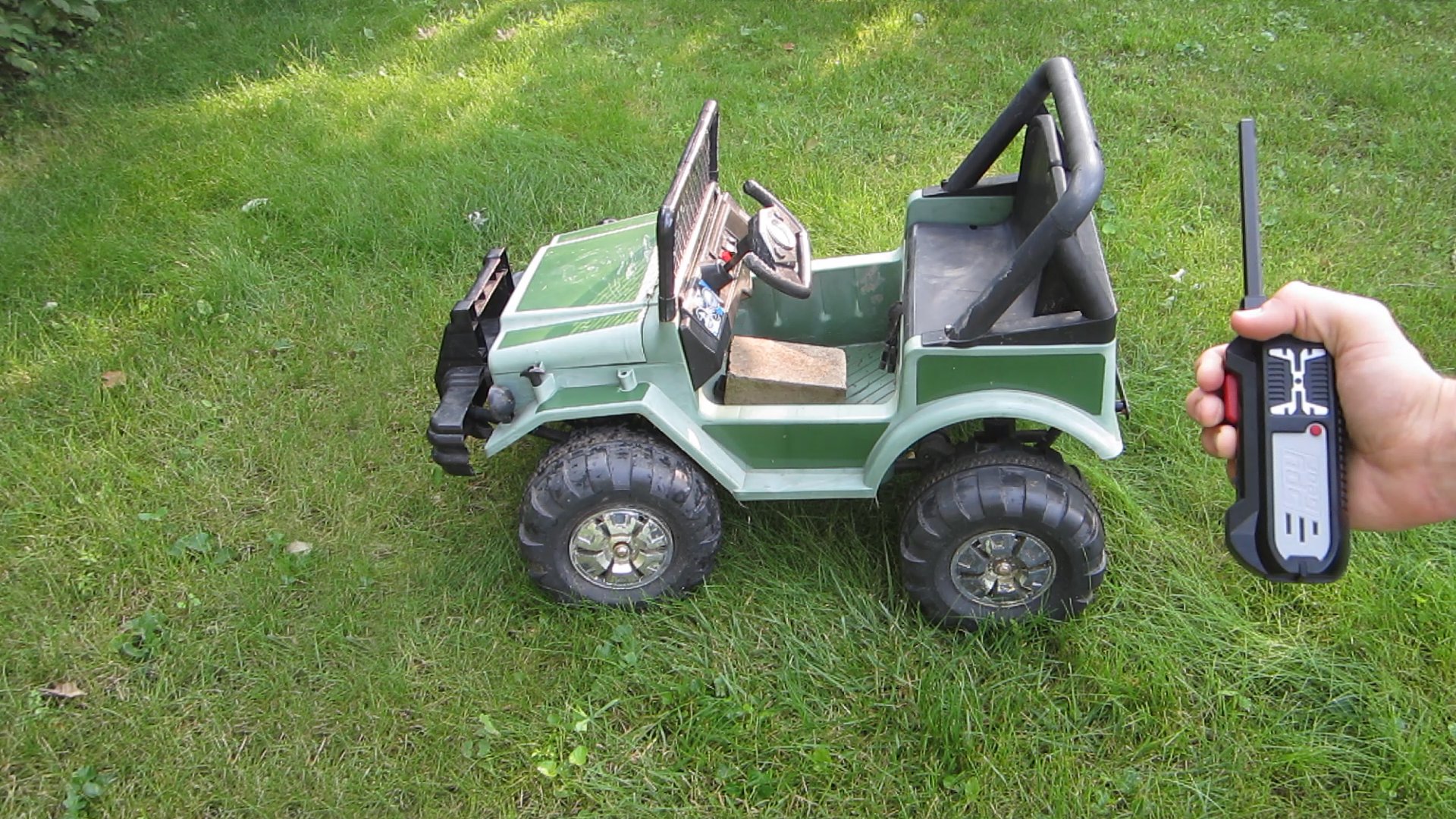
There are a lot of times when it’s useful to be able remotely turn something on or off. In this instance, my son has a small Power Wheels car. I wanted to be able to turn the car off if he drives too far away, or in the wrong direction. So I designed a simple remote kill switch, which lets me turn the car (or anything else) on and off with a remote. As an extra safety feature, if the car goes outside the range of the remote, it will automatically turn off.

YouTube player

See the project on Instructables: instructables.com/id/Remote-Kill-Switch/

What will the next generation of Make: look like? We’re inviting you to shape the future by investing in Make:. By becoming an investor, you help decide what’s next. The future of Make: is in your hands. Learn More.

Project Steps

Select a Radio Transmitter and Receiver

The first thing that you need to do is find a suitable radio transmitter and receiver. You can use an RC car, an old pair of walkie talkies, a wireless doorbell, or anything that you have lying around. The only requirement is that it needs to be able to send and receive a constant signal. For example, a walkie talkie will continuously transmit a signal as long as you are holding down the send button.

For the best results, try to find a transmitter and receiver that has a long range and doesn’t pick up a lot of interference.

In this example, I am using a pair of spy gear walkie talkies.

Modify the Receiver

In most cases your receiver will need to be modified a little bit.

You need connect to the output of the receiver. In this case, I am using a walkie talkie and the output is connected to a speaker. The output signal is a series of pulses that are sent to the positive terminal of the speaker. The negative terminal of the speaker is connected to the ground of the receiver. We need to connect to both of these wires, so I cut the wires going to the speaker. Then I stripped the insulation off of the ends.

I also cut off the call button from the receiver because it wouldn’t be used.

The Control Circuit

The control circuit that I designed for this project uses a 741 OP AMP to monitor the output of the receiver. Two series resistors (3.3kohm and 1kohm) form a voltage divider which sets a reference voltage that the OP AMP uses for comparison. These resistors may need to be changed to calibrate for your receiver. When the output voltage of the receiver goes above this reference voltage, the output of the OP AMP goes HIGH and activates the relay.

I am using an automotive relay so that it will be able to switch high currents (up to 40 amps). However larger relays like this also require more current to activate. The OP AMP can not output enough current to activate the relay by itself. So the output of the OP AMP is connected to a power MOSFET. This transistor is used to turn the relay on and off.

I added a diode, a capacitor and a resistor to the input of the control circuit to help filter out noise and to smooth out the pulses from the radio receiver. This prevents the control circuit from rapidly turning on and off.

The control circuit is powered by a 12-volt battery pack.

When assembling the circuit, I first prototyped it on a breadboard. To test the performance of the circuit, I connected an LED to the output. Once I was happy with how the circuit was working, I soldered it onto a printed circuit board.

Create an Adapter to Power the Receiver (optional)

The control circuit requires a battery and the receiver requires a battery. If they use the same voltage, then you can just connect them together in parallel. But if they require different voltages, then you either need two batteries or you need to make an adapter for one of them.

In this case, the receiver required 9 volts and the control circuit required 12 volts. So I used a voltage regulator circuit to bring the 12 volts of the control circuit battery down to 9 volts. This let me power them both with one battery pack.

I used an LM317 variable voltage regulator. This chip uses two resistors to set the output voltage according to the formula: Vout = 1.25 x (1 + (R2 / R1)). Using a 1.5kohms and a 240 ohms brought the output down to about 9 volts. Then I used a 9-volt battery connector to connect it to the receiver.

Add a Latching Switch to the Transmitter

If your transmitter is activated by a momentary switch, then you need to replace it with a latching switch, so the transmitter will stay on without you having to hold down the button. In this case, I am using the call button on a walkie talkie.

Locate the button and desolder the wires from it. Next, solder a latching switch in its place. I recommend using heat shrink tubing to insulate the connections.

Now you need to cut a slot in the side of the housing for the new switch. Hold the switch up to the side of the housing and mark the two ends of the switch. Then us a sharp knife to cut a slot that us just big enough for the slider on the switch.

Lastly glue the switch in place. Be careful to not accidentally glue any of the moving parts on the switch.

Attach the Relay

I am using an automotive relay. These typically mount to a special automotive relay socket. But you can also use individual 12-10 gauge quick disconnect connectors.

First we need to connect the relay to the control circuit. Take two wires and strip the insulation off of the ends. Solder one of the wires to the output of the control circuit and solder the second wire to the ground (negative terminal) of the control circuit.

On the other end of the wires, crimp on the 12-10 gauge connectors. Connect these to the terminals on the relay that are attached to the relay’s coil.

Now you need to attach the device that you want the remote kill switch to control. In this case that was a power wheels car. I cut one of the wires that goes from the battery of the car to the power switch. Then I stripped the insulation off of the cut ends and crimped on another set of connectors. I attached one of these connectors to the common terminal on the relay and I attached the other connector to the “normally open” terminal on the relay. With this setup, the battery of the car will be disconnected until our circuit activates the relay. This way if the car goes outside the range of the remote, it will automatically turn itself off once it stops receiving the signal from the transmitter.

Mount All the Parts

The last step is to mount all the parts to the device that is being controlled. Fortunately, there was a lot of empty space in under the hood of the power wheels car. So I attached all the components to the walls with duct tape. You want to make sure that everything is secure so that the parts don’t bang around when it starts to move.

Use Your Remote Cutoff Switch

Now you are ready to use your new remote cutoff switch. Turn on the transmitter and the receiver, then flip the switch on the transmitter to begin sending the control signal to the receiver. The car should turn on. When you want to turn off the car, you can just turn off the transmitter. The car will also turn off if it goes outside the range of the transmitter.

Keep in mind that this system is susceptible to various kinds of interference. You should not rely solely on this system to keep you or anyone else safe. Even with this kill switch, You should still keep a close eye on your kids and be prepared to run up and save them if they need it.