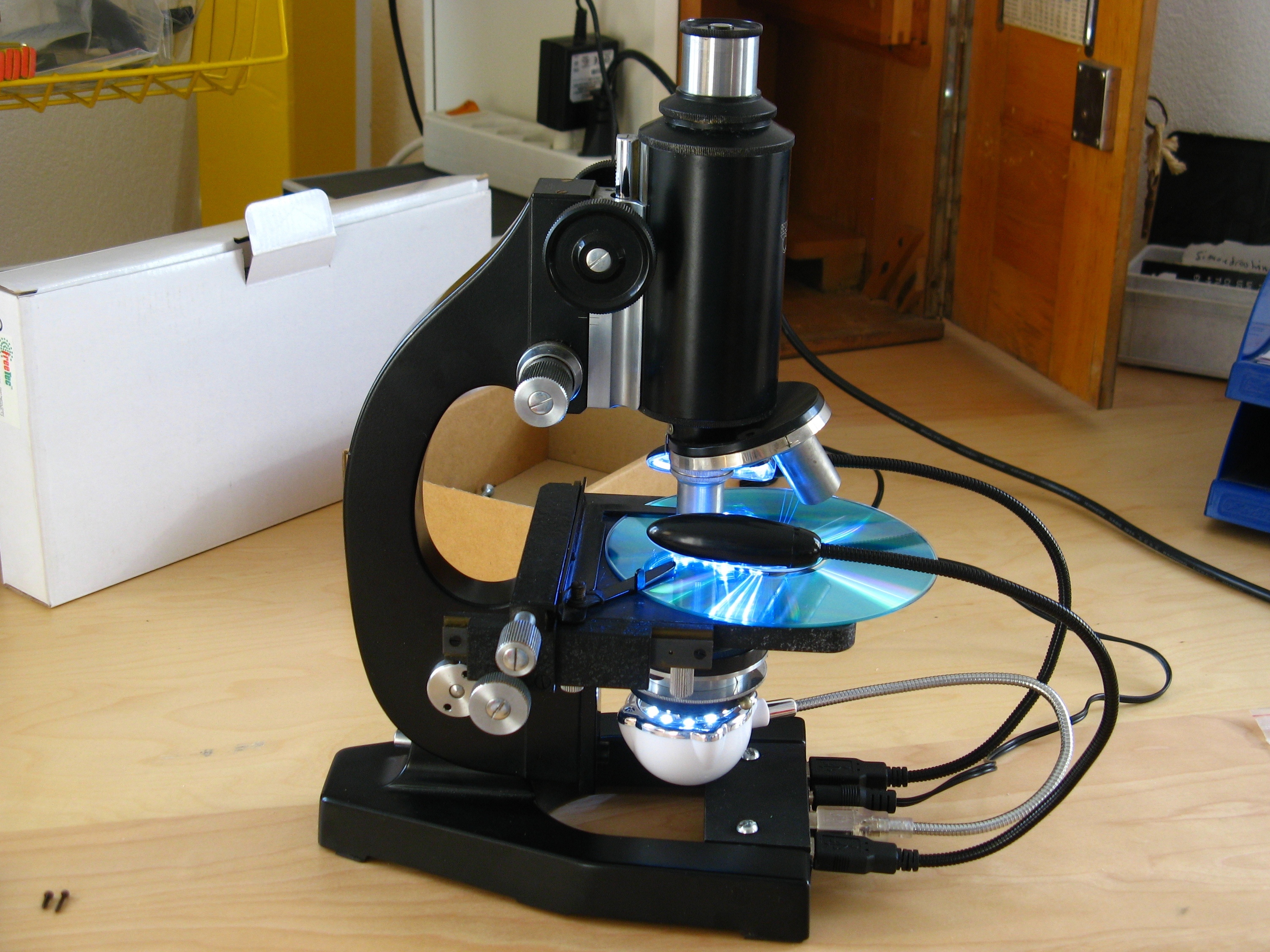
My girlfriend got a microscope packed in a really nice wooden box, which also provides space for all the additional lenses and working materials. But the uses for the microscope were really limited, especially because I rarely have transparent stuff to look at and there was no light bulb built in. It is a nice traditional microscope with a mirror in the bottom to capture sunlight.

Retrofit

So it was clear that this microscope needed a proper light source in the bottom and additional adjustable lights from the top for viewing non-transparent objects.

Lamps

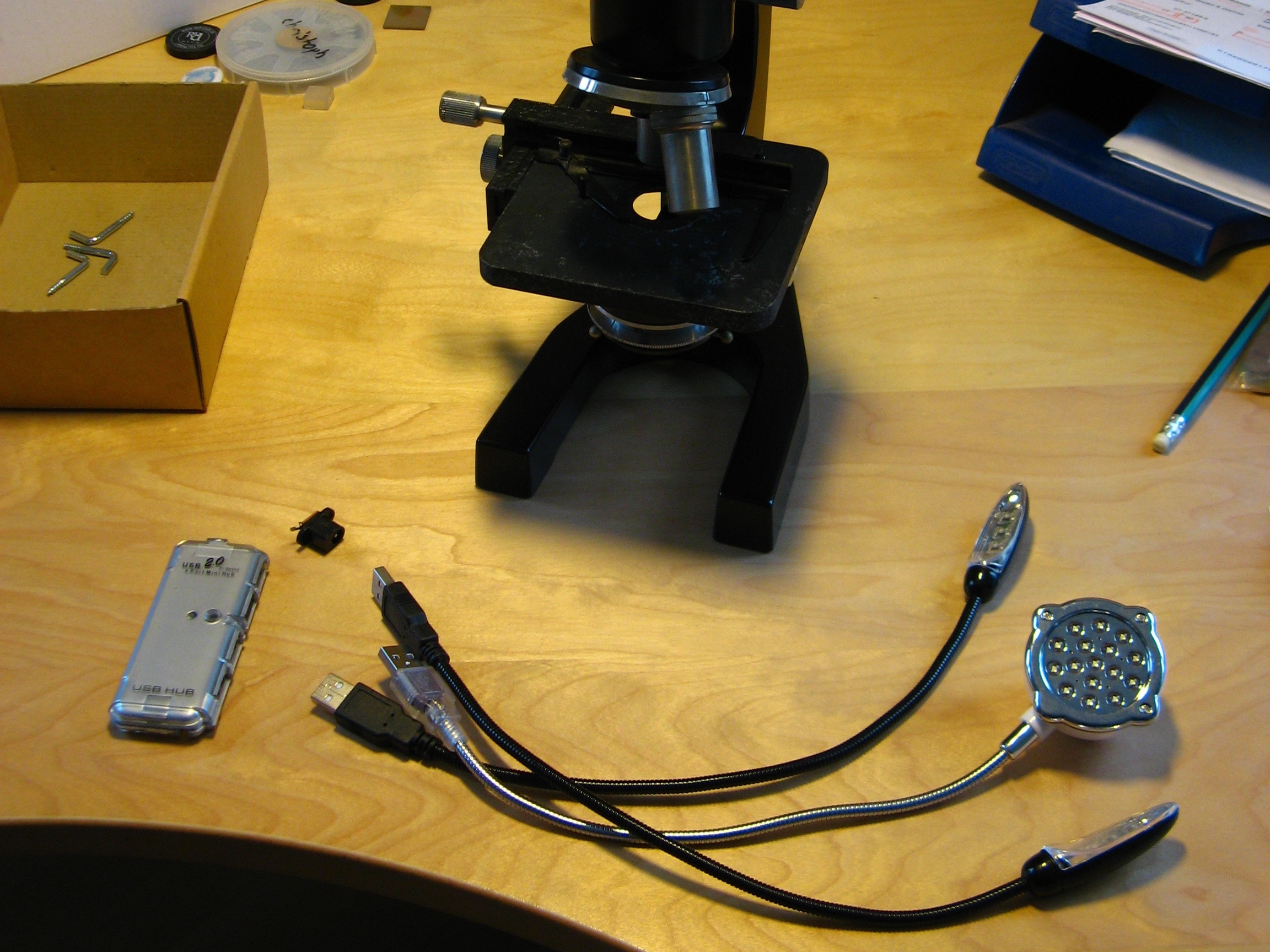
Early on I had in my mind that I needed gooseneck lamps to be able to adjust the lighting to my needs. The cheapest gooseneck lamps you can get are laptop keyboard lamps with LEDs, which you connect to a USB port. I bought mine directly in China but they are also quite cheap at computer/electronic discount sites. All they need is a power source and a mechanical support. For this I used a USB hub. You also can get really cheap ones (and, as with the hub I had on hand, the performance is often bad, which is why I sacrificed it). So my total budget for this project was around $8 US for the three gooseneck lamps.

What will the next generation of Make: look like? We’re inviting you to shape the future by investing in Make:. By becoming an investor, you help decide what’s next. The future of Make: is in your hands. Learn More.

Project Steps

What you will need

Pictured here is what you mainly need for this project: three gooseneck LED lamps, one small USB hub, and a power connector. It is possible that your USB hub already has a power connector built in; if so, simply use that one.

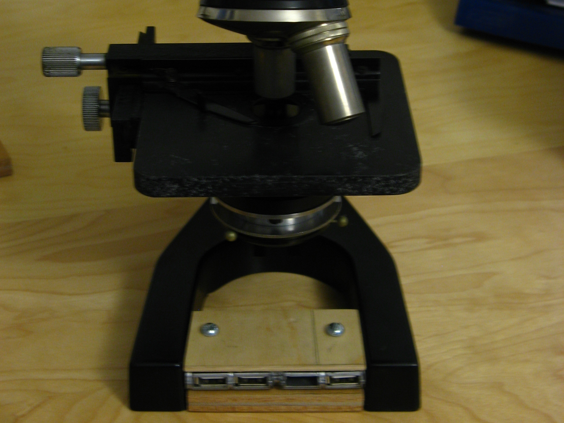
What else you need depends on on your microscope. For mine it was enough to cut the case of the hub on both sides a bit and use some plywood to make a “sandwich” that press-fits between the legs of the microscope base. This sandwich forms a good-enough lamp support.

Make the LED lamp support

Decide where you would like to place the USB hub on your microscope and in which direction the USB ports should be oriented.

Make a plan for how you would like to fix the USB hub in this position. I had to find a solution that was not permanent (to be able to remove my modification and leave behind the untouched “historical” microscope). You can use what you have at hand, screws, adhesive tape, super glue,…

I decided to place the USB hub between the legs of the microscope base with all ports to the back. I had to make sure that nothing from the lamp support is higher than the legs because otherwise the microscope would not fit anymore into its nice storage box.

Mark the width between the legs on the two plywood pieces and use the USB hub to mark the needed depth. Cut them into size with the hacksaw or similar.

Use your plywood pieces, which now fit nicely between the microscope feet, to mark the width on the USB hub. Use the hacksaw to cut away what is unneeded.

Use two C-clamps to hold all three pieces together and drill two small holes from top to bottom through the plywood piece. Screw two wood screws into these holes.

Add the power connector

Remove the wood screws and the two plywood pieces.

Open the USB hub. Normally you find screws somewhere (also look under the labels and rubber feet, which we don’t need anyway).

Use the multimeter to make sure there is no short circuit between the USB power and ground. This happens really easily when you cut and drill into the PCB. Try to remove any junk left from the edges of the PCB and the drill hole. In my case I had to desolder a cut-in-half capacitor which made a short circuit.

Decide where and how to place the power connector. If your hub has a power connector it is possible that it is now in the wrong place.

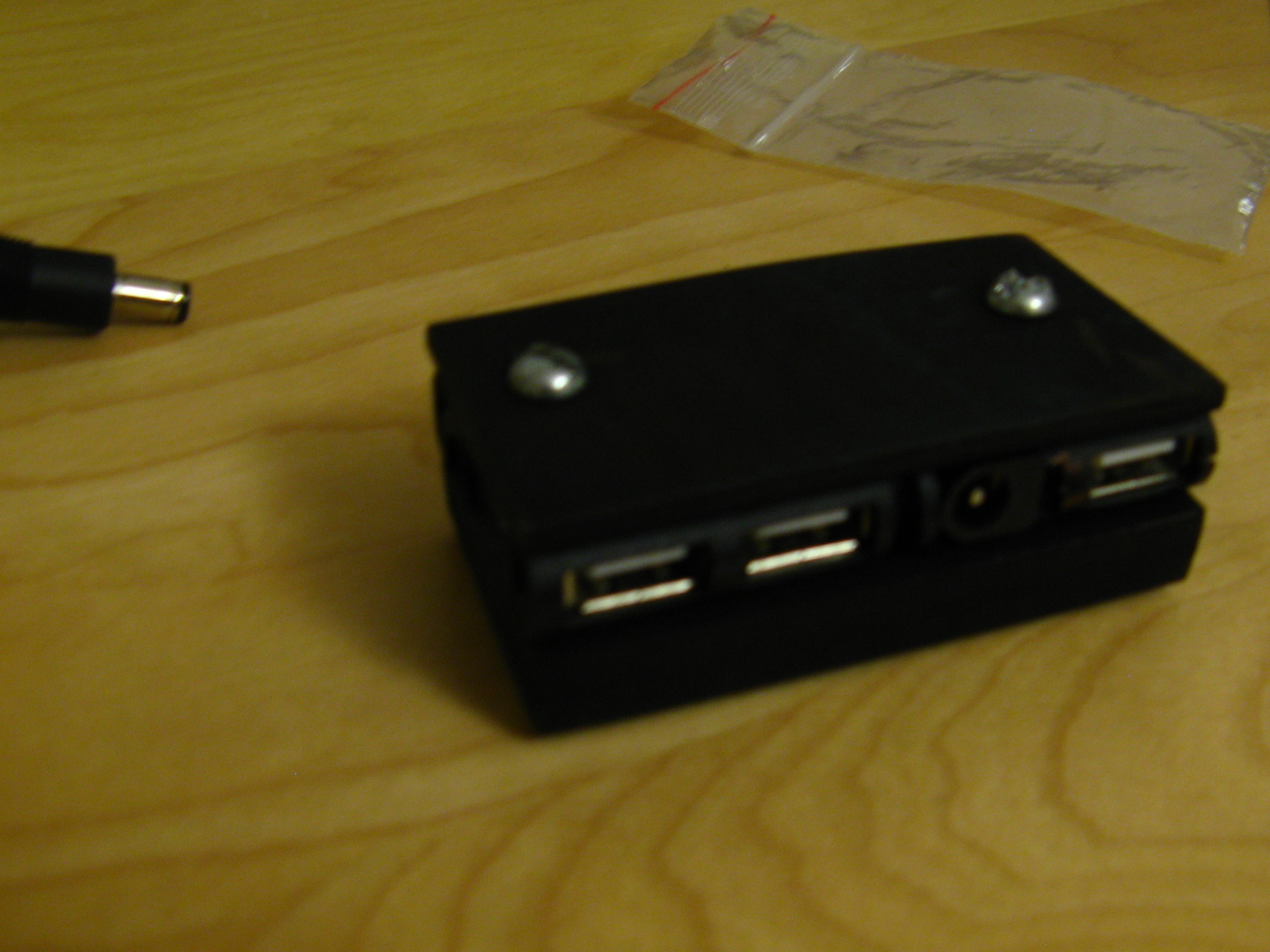
In my case the hub didn’t have a power connector and I had to add one. To make space to put the connector into the case, I desoldered one of the USB connectors (I only need three), removed some PCB that was in the way, and voilà — there was a space for the power connector.

Connect the power connector to the USB hub. You can use the solder points from the USB connector for this or the solder point where the power plug was connected before. If you like you can add some glue to protect the connector and the solder joints from mechanical stress.

Plug in the wall adapter and test the modified hub with your lamps.

Assembly

Paint the wood pieces and the USB hub case. I made mine black to match the color of the microscope. If you like, you can also paint the screws.

Put together the modified USB hub.

Screw the “sandwich” together.

Add the finished lamp support to your microscope.

If you like, add some rubber feet under the lamp support and the microscope. (Mine had just the bare metal to stand on before.)

Add the gooseneck LED lamps and connect the wall adapter/power supply.

Have fun testing your new retrofitted microscope!