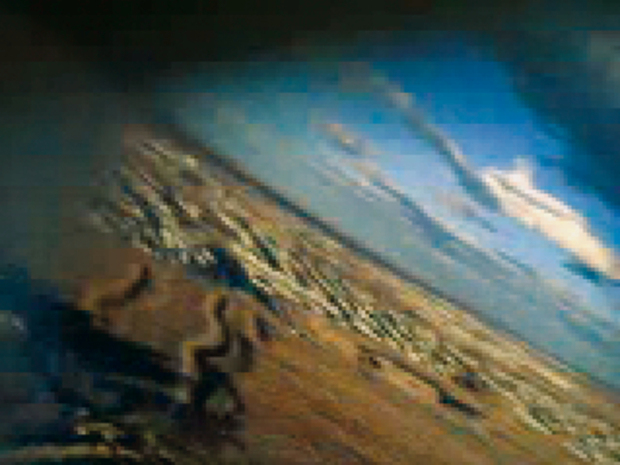
Camcorder rocket

Hack a $30, single-use camcorder to make it reusable, then launch it up in a model rocket and capture thrilling astronaut’s-view footage of high-speed neighborhood escape and re-entry.

You can build this project over a weekend and the results are fantastic. The idea goes back to 1929, when Robert Goddard launched the first scientific payload on a rocket: a still camera and a barometer. During the height of the space race, model rocketry supplier Estes offered a tiny Super 8 film kit that recorded about 10 seconds of rocket POV action. Today, Estes sells a launchable DV recorder called The Oracle, but it costs $120 and its image quality is lacking.

We’ll do much better with a new camcorder that costs only $30, is very light, and has enough memory for several flights. It was designed for single-use only, but we’ll make it reusable.

For a DIY version of the launch pad, check out the Portable Model Rocket Launch Pad project.

What will the next generation of Make: look like? We’re inviting you to shape the future by investing in Make:. By becoming an investor, you help decide what’s next. The future of Make: is in your hands. Learn More.

Project Steps

Build the rocket body.

Follow the instructions to assemble your model rocket kit.

After any gluing and painting steps, you can skip ahead and work on installing the camcorder in the nosecone.

Disassemble and strip down the camcorder.

The CVS camcorder is already small, but it’s still too heavy to fly in most rockets. By removing everything that isn’t essential, we can cut its weight down from 140 grams to 21 grams (without batteries).

Remove the camcorder’s battery cover by inserting something pointy into the opening on the bottom while sliding the cover off.

Unlock the grey battery holder and remove it.

Unpeel the sticker on the back and use a small Phillips screwdriver to remove 4 screws, one at each corner.

Snap apart the case. Inside is the main circuit board.

Remove the 2 screws at the 2 points shown here to release the circuit board.

Find the small 4-pin connector that connects the circuit board to the batteries. Pull straight up to remove the board.

Optional: Remove the speaker, which is encased in a vibration-resistant rubber housing glued to the circuit board. Just pull it to remove, and cut or unsolder the speaker wires.

Removing the speaker saves 2 grams, which doesn’t seem like much, but every bit counts on smaller rockets. Leave the microphone in place, though, to record the roar of takeoff.

Rig the camera interface.

The camera connects to a computer using USB protocol, but instead of a standard USB port, it has its own card-edge connector that we’ll need to wire into. We’ll save flying weight by using 2 USB cables, a short one that’s attached to the camera and ends in a lightweight connector, and a longer, second cable that connects the lightweight connector to your computer’s USB port.

Cut and strip a short section of the USB cable. Solder the red, black, green, and white leads to the mainboard’s edge connector, contacts 6-9, respectively. (If the computer indicates a problem later, your cable may not have the standard color-coding, and you should try swapping the green and white wires.)

This cable makes the same connections as the cable for the Dakota Digital camera in MAKE, Volume 03 (“Cheap Shot,” by Charles Hoffmeyer, page 130).

Solder or crimp the 4 leads to one of your power connector pairs, and solder or crimp the other connector to the computer end of the USB cable, preserving the wire ordering.

My connectors weren’t designed to be taken apart that often, but shaving down the locking tabs made them disconnect more easily.

Plug the cable into the computer. Windows XP should identify it as a “Saturn” and prompt you to install drivers. These drivers don’t exist yet, so hit “Cancel.”

If the computer gives an error message and cannot identify the camera as a “Saturn,” swap the green and white USB connections.

Browse to camerahacking.com. Under “CVS One-Time-Use Camcorder,” click “FAQs & Links,” and choose some up-to-date driver software. Carpespasm, BillW, and Corscaria have good wares, among others (and I wrote a Mac downloader that works with the oldest version of the camera, 3.40). Install per instructions.

Record a video and test it. It will be in XVID 1.0 format, 320×240 resolution, 30 frames/sec. After you’re able to download videos from the camera, you may need to install a video codec to play them back; I recommend MPlayer from http://www.mplayerhq.hu.

Mount the camera in the nosecone.

Now we’ll put the camcorder in the nosecone. This is the most protective part of the rocket, and adding the weight in the front will help stability during flight. There are many ways to secure a camera so it won’t come off during liftoff, including styrofoam and glue, but this method is reversible, which I prefer.

Cut a hatch in the side of the nosecone, for inserting the camera. I taped a 3″×2¾” piece of paper to the cone to use as a template. We will be replacing this hatch; so don’t cut any more than necessary.

The hatch should be big enough to let you operate the camera. Don’t cut all the way to the bottom of the cone; leave a ring above the base to keep it strong. If you mess up, you can buy a replacement cone.

Make 4 threaded standoffs by gluing M1.8 nuts into the unthreaded standoffs. (The circuit board’s mounting holes are so small that I couldn’t find threaded nylon standoffs that would fit.) Screw the standoffs onto the board.

Score the inside of each standoff to give the glue something to attach to. Make sure the glue is fully cured before screwing the standoffs on.

Cut the standoffs so that they match the curve of the nosecone. Start with 2 short and 2 long.

Use the rocket body to mark them, and cut them more precisely, angled to fit.

Solder the battery holder’s negative lead (black) across the 2 pins closest to the lower-left corner, near the on/ off button.

Solder the positive (red) lead to bridge the adjacent 2 pins, near the mystery-chip blob.

If you’re using an N battery holder with a CR2 battery, cut the sides off of the holder to let the battery seat. CR2s are the same length as Ns, but wider.

Cut a peephole in the side of the nosecone and verify it with the camera’s viewfinder.

The closer you can mount the lens to this hole, the smaller it can be. But don’t worry about the size yet — you can enlarge it after the camera is glued into place.

Verify that everything fits, the camera lens aligns with the peephole, and there’s enough wire to reach the battery holder, which you’ll mount below.

Mark where the standoffs will glue to inside the nosecone, and rough these spots up. I used a knife to cut a crosshatched pattern.

Glue in the standoffs and double-check that the camera can still see out the hole. Use C-clamps to hold the board in place while the glue foams up. Allow to cure completely.

Polyurethane glue requires moisture to cure, so I put a small wet paper towel in the cone.

After the initial application of glue cures, add some more to reinforce the standoffs.

Optional: If you want a view of the ground as the rocket lifts off, install a rearview mirror on a small nosecone, attached in front of the peephole. The reflection will make the body of the rocket appear at the top of the picture. If you want the body at the bottom of the picture, you can mount the camera upside-down, or correct the videos digitally later. Cut a plastic View-Master mirror down to size with wire cutters. After the glue has set, trim around the mirror with a hobby knife and file.

View-Masters (and SLR cameras) use front surface mirrors, where the coating is on the front of the plastic (or glass). This prevents image ghosting, but the shiny coating is easier to scratch.

Optional: To save even more weight, remove the LCD viewfinder. Remove the camera circuit board from the nosecone and unscrew the 2 screws that hold the screen on the back. Slide the gray plastic catch on the screen’s ribbon cable (I used 2 small screwdrivers to help), and pull to completely disconnect the screen and cable.

Install the battery.

Battery holders have no springs on the positive terminal, so a good whack upon landing can pop the battery out, interrupting the current. If this happens before you press the Stop Record button, you may write garbage to the camera’s memory chip and lose your entire recording, or even render the camera inoperable. To prevent this, I strung a small wire through the positive terminal of the battery and connected it to the positive terminal of the battery holder. That way, if the battery is knocked loose, the wire still keeps it connected electrically.

Thread some thin wire through the vent holes on the positive terminal of the battery. If you don’t have wire small enough, use a few strands from a larger, stranded wire.

Load the battery into the holder and connect the wire to its positive terminal. Glue the holder into the bottom of the nosecone, below the hatch opening.

Cut 2 small holes through the bottom of the cone and thread a cable tie through the holes and over the battery, to hold the battery in place. Because the battery is mounted perpendicular to the direction of flight, the cable tie will absorb most of the shocks.

Finish the nosecone and complete your rocket.

Referring to the camera’s original housing, label the Power and Record buttons on the bare circuit board so they are easy to use.

Add some tabs to be able to close the hatch securely. Glue 2 thin strips of credit card plastic inside the cone along the sides of the hatch. Glue 2 smaller pieces to the front of the hatch itself, and a third small piece inside the nosecone, to fit in between. When done, the hatch should sit flush with the nosecone.

Make sure you reinforce the hatch at the bottom, to keep it securely in the rocket, and at the leading edge, where it will bear the most pressure.

Plug any holes in the bottom of the nosecone by gluing more pieces of credit card plastic.

At the top of the rocket’s flight, a small explosive charge fires in the rocket motor to pop the nose off and deploy the parachute. Holes in the bottom of the nosecone can vent pressure without popping the cone, which will send your rocket crashing into the ground!

Did you ever wonder why rocket fins stick down past the tail? The reason has to do with stability, which you need to understand if you are modifying a rocket kit.

Two imaginary points determine whether a rocket will fly straight or corkscrew hopelessly out of control. The first point is the center of gravity (COG). If you were to place your rocket on a razor’s edge, this is the point where it would balance. Add weight to the nosecone and the center of gravity moves toward the nose; add bigger engines and it moves rearward.

The second point is called the center of pressure (COP), and it is a little harder to explain. This is similar to center of gravity, except it involves the aerodynamic forces balancing out. If you were to trace the 2-dimensional side-view of the rocket onto cardboard and then cut it out, it would balance near the center of pressure. Enlarging the fins and extending them down moves this point rearward.

Once you know these two points, you can estimate the rocket’s stability. The general rule for stable flight is that the COG must be at least one body diameter in front of the COP. During flight, aerodynamic forces will push rearward on the COP. If it isn’t already behind the COG, then the rocket will attempt to turn around, which is bad news. If the COP is behind the COG by just a little, the flight will be marginally stable and probably corkscrew.

For this project, we won’t be modifying the outside too much, so the COP will remain the same. We will be adding the weight of the camcorder to the nosecone, moving the COG forward. Aerodynamically, this will only make the flight more stable.

Launch sequence.

If you are using a smaller engine, you may want to do a final weigh-in before going ahead with a launch. With everything installed, verify that the total weight is within the capability of the rocket motor. If so, follow the rocket kit’s launch instructions. Here’s the basic sequence:

Check to make sure that the nose fits securely, but not too tightly. Then tie up the parachute, engine, and wadding.

Set up the launch pad per instructions. Make sure the field you are launching in is large enough; otherwise you’ll lose your precious payload. For a rocket powered by a D-sized engine, the field should be at least 500 feet in diameter.

Ensure that the rocket launcher is not armed (usually this means the key is removed) and then set up the rocket on the pad.

Turn on the camera and press the record button. The red record light, just under the lens, should come on.

Close the hatch and tape it closed. Although not typically rated for space-faring use, ordinary masking tape works fine.

Start the countdown and launch.

Recover the rocket. Open the hatch and press the Record button to stop recording. The recording light should turn off. Then turn the camera off by pressing the On/Off switch. If you forget to turn the camera off, it will switch off automatically after a few minutes of non-use. Do not turn the camera off by removing the battery.

Back at your computer, hook up the USB cable, download the video, and enjoy.

Conclusion

This project first appeared in MAKE Volume 07, pages 78-89.