A garage door opener openly displayed inside your car can be an incentive to thieves. Documents from the glove compartment are likely to reveal your home address, and with the remote in hand a thief can help him- or herself to the contents of your garage, and (if it’s an attached garage) secure a concealed location from which to attack one of your house’s exterior doors. Together with other conspicuous valuables, a visible garage remote–say, clipped to the sun visor–can make the difference between a thief choosing to break into your car and choosing to move on to the next one.

Sure, you could just pop the remote in the glove compartment when you get out. But having it immediately accessible is convenient, and it’s easy to forget or get sloppy in your concealment habit.

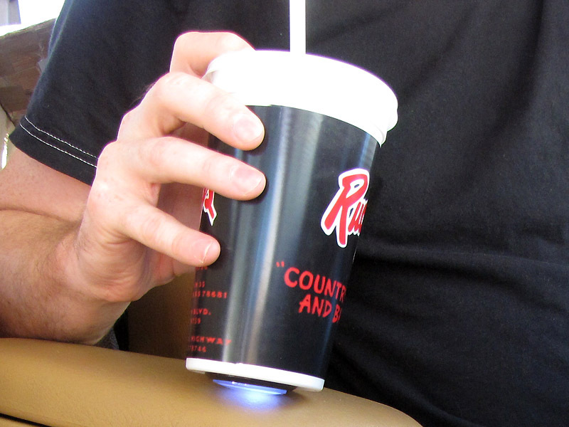
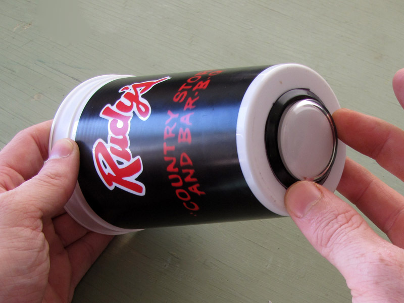
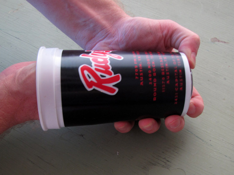
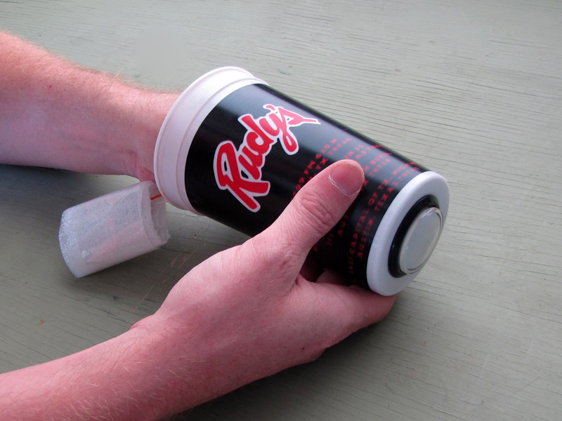
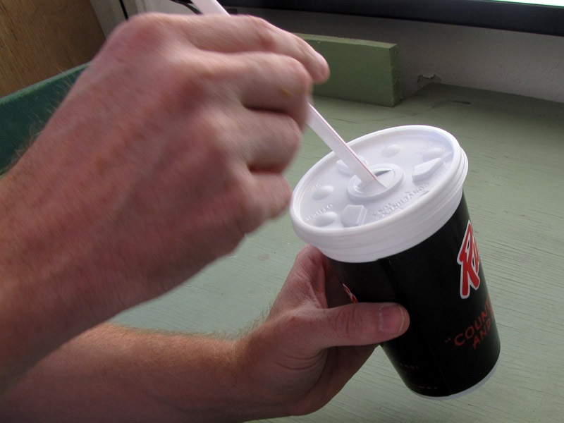
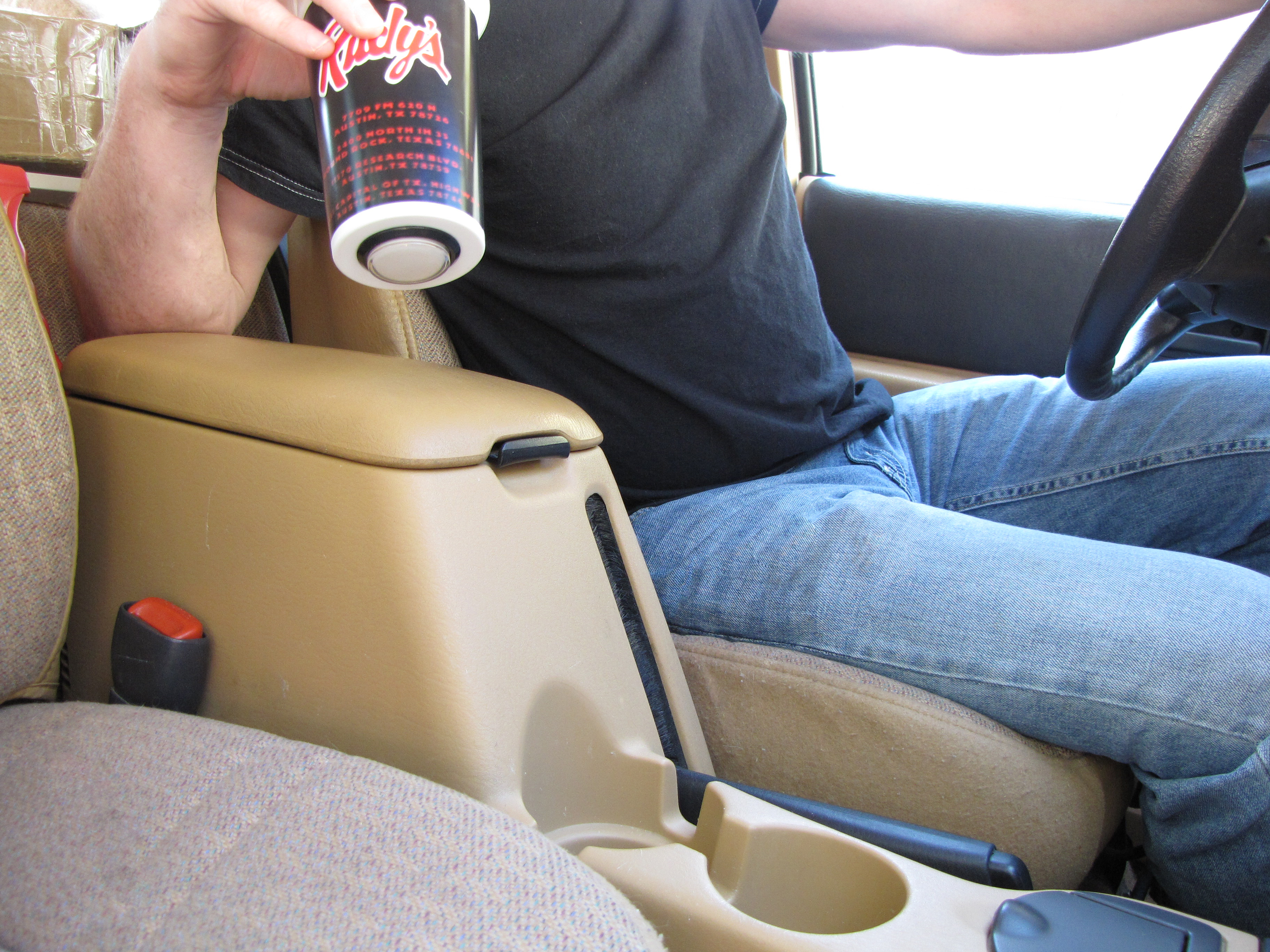
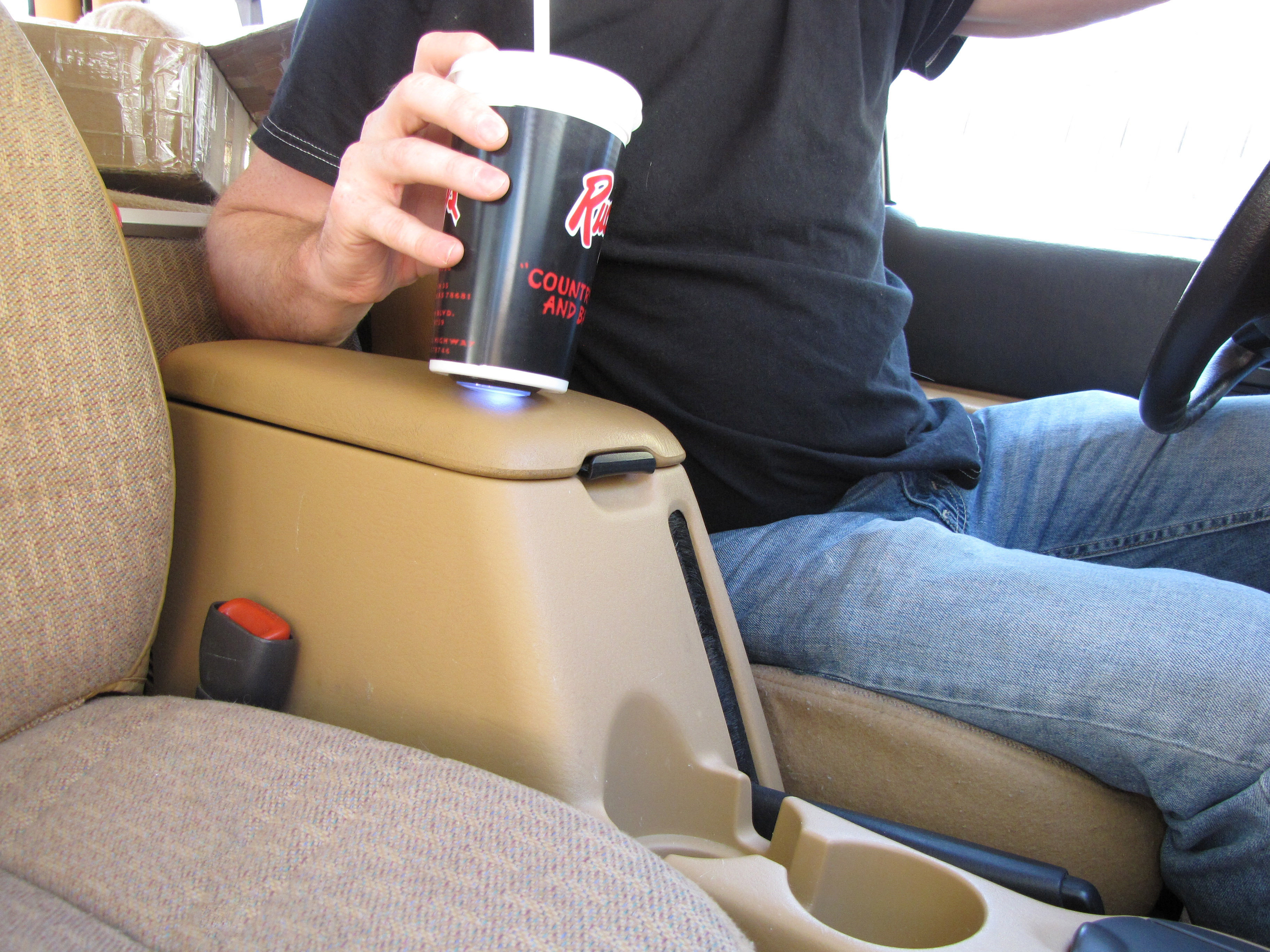
This easy garage door remote mod retains all of the convenience of the remote clipped to the visor while dispelling most of the risk. The remote button is concealed on the underside of a plastic beverage cup that rests in your cup-holder, with the electronics concealed inside the cup. To activate the opener, just push down on the top of the cup. From outside of the car (and from inside it, too), the remote looks like an empty soda cup you just haven’t thrown out yet.

What will the next generation of Make: look like? We’re inviting you to shape the future by investing in Make:. By becoming an investor, you help decide what’s next. The future of Make: is in your hands. Learn More.

Project Steps

Cut a hole in the bottom of the cup

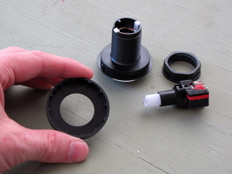
Dismantle the button into its four main components: the button housing, the hex nut, the switch itself, and the “ferrule,” which is the round thing I’m holding in the picture.

To remove the switch itself, hold the button housing stationary while twisting the switch counterclockwise as viewed from the back side of the button. To re-install the switch, reverse this procedure.

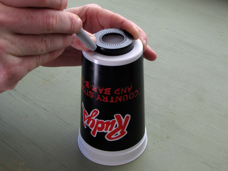
Center the ferrule on the underside of the plastic cup and trace around it with a marker.

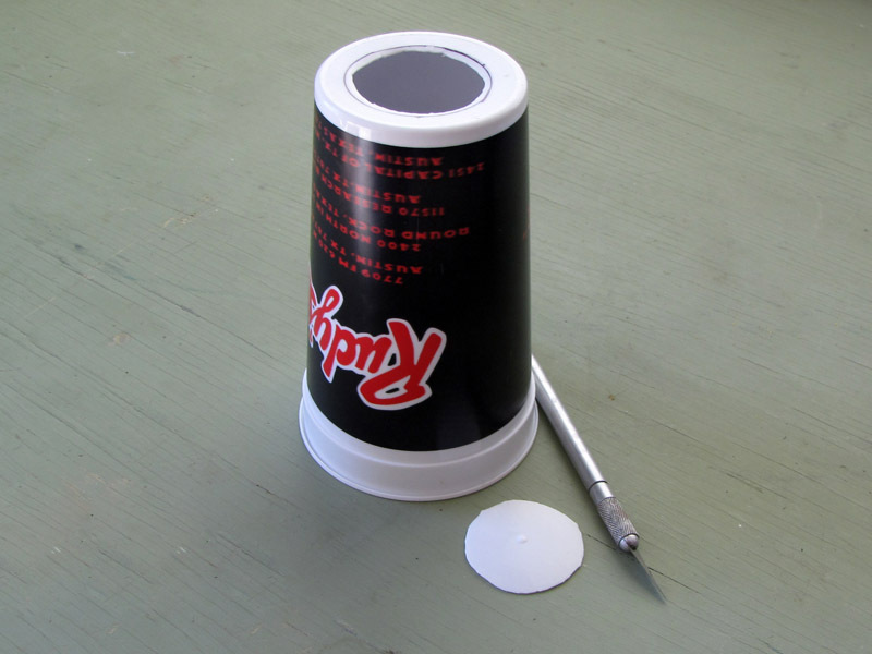
Cut out the hole with a hobby knife, leaving about 1/8″ inside the black line.

Install button in cup

Insert the button housing from the bottom of the cup. The bezel should sit flush.

Reach into the cup and slip the ferrule back around the button housing.

Reach into the cup, thread the hex nut around the button housing, and tighten it down against the ferrule. The button housing should now be secure inside the cup.

Disassemble garage remote

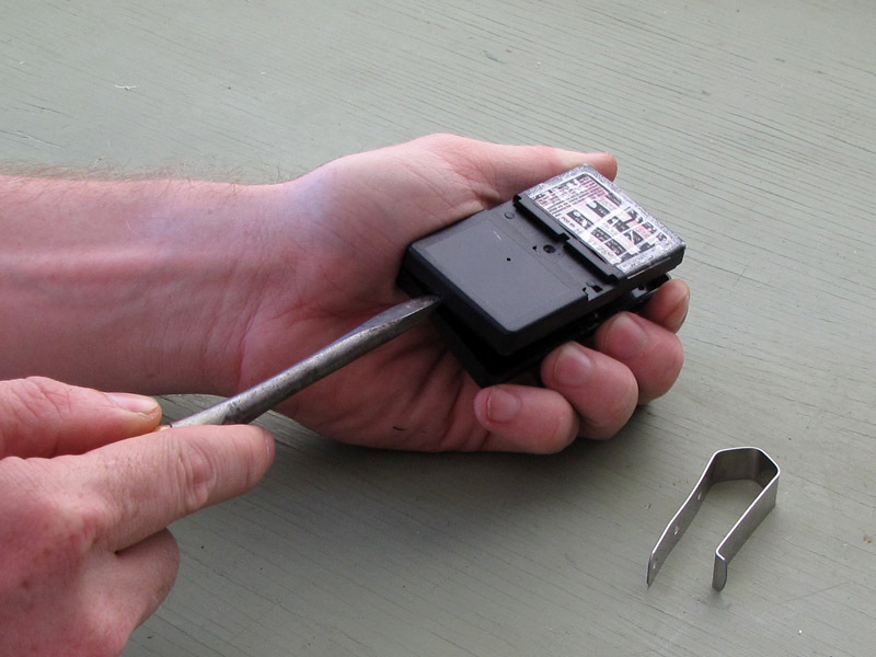
Remove the case. Mine was a snap-together clamshell design that opened easily on prying with a flat-blade screwdriver. Yours may have screws you will have to turn out.

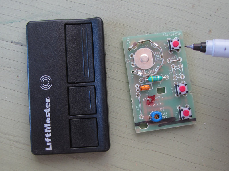
Remove the circuit board. Mine just lifted out, but again, you may need to remove a screw or two.

Identify the door button. This should be easy, as there probably will only be one. If not, just test them.

Use caution, of course, when working on a remote with the battery installed. The battery currents and voltages are harmless, but it’s likely you’ll accidentally activate the garage door once or twice. Be sure the area around the door is clear of obstructions, children, and pets.

Install pushbutton leads

Pick two solder pads attached to the door button. Short them with a small jumper wire and verify that the garage door is activated.

If you want, it wouldn’t be hard to de-solder the remote’s factory button from the PCB. I left mine in place, to make it easier to restore the remote to its original condition if I want to.

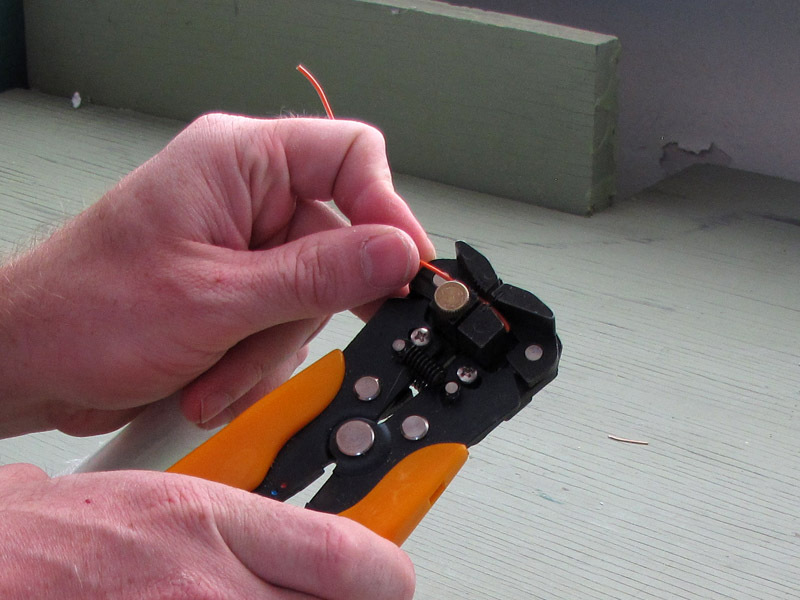
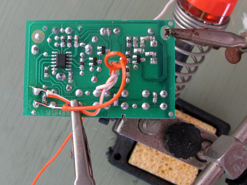
Strip both ends of two 8″ pieces of ~20AWG hookup wire. Solder the leads to the pads you tested earlier.

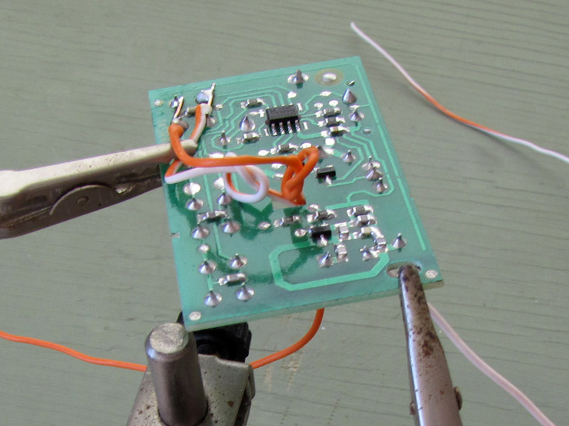
Arrange for strain relief on the button leads, so pulling on the wires doesn’t rip them off the solder pads. My PCB had a handy-dandy hole in the middle of it for indexing to the case, so I just tied a couple of loose knots in the button leads and threaded them through it. Now, pulling on the leads puts strain on the knots and the board as a whole, rather than the relatively fragile solder joints at the pads.

Pad the PCB

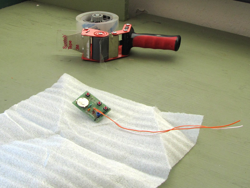
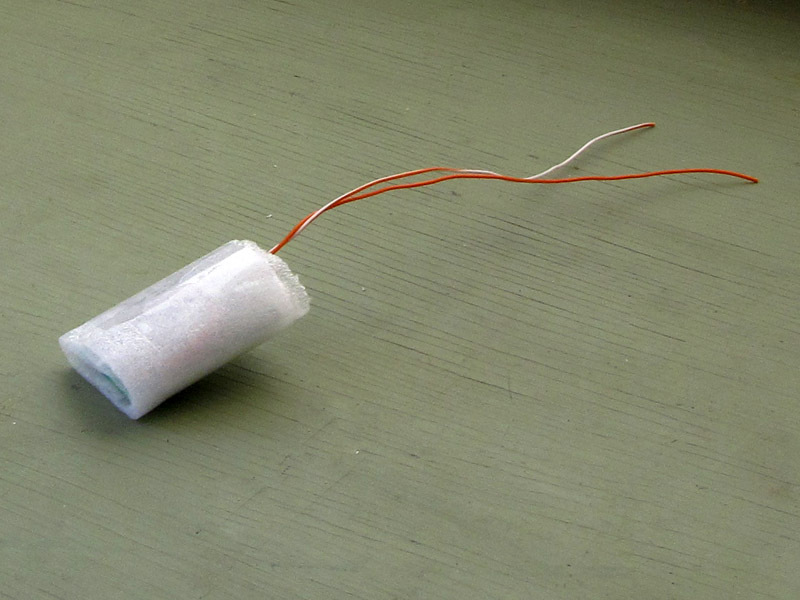
Make sure a good battery is installed, and wrap the PCB in nonconducting foam or bubble wrap, with the button leads hanging out.

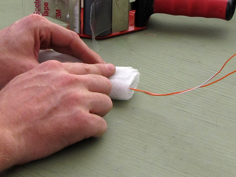
Secure the padding with packing tape.

Connect the PCB to the button

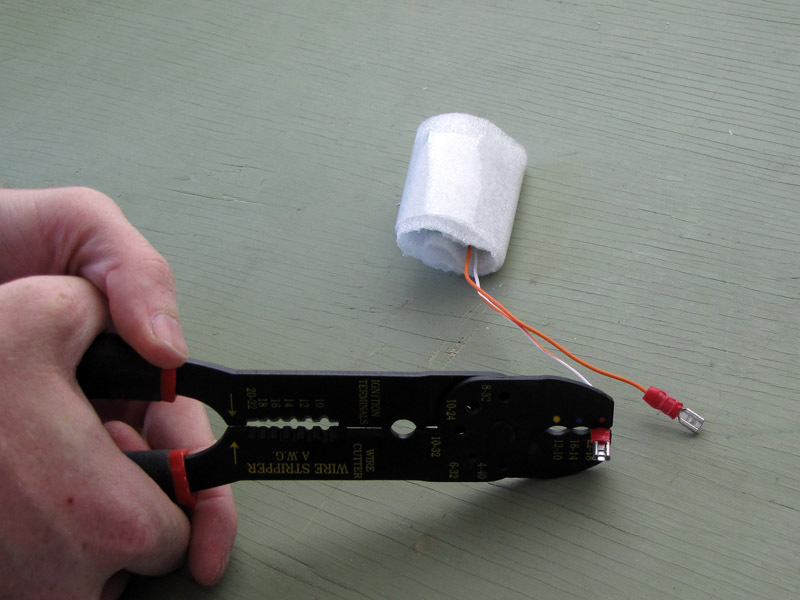
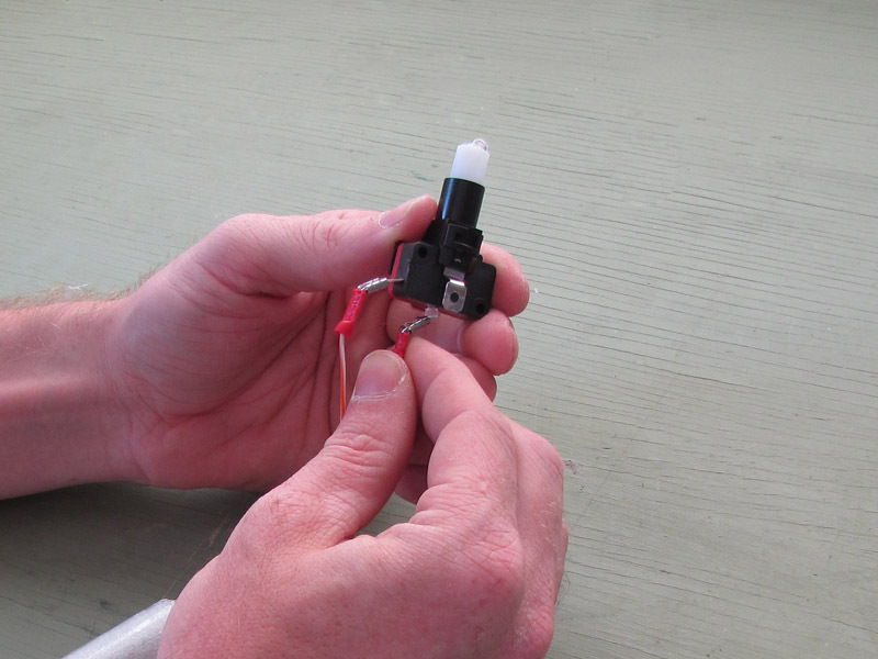
Crimp a female quick-connect to the bare end of each wire from the PCB. If you don’t have quick-connects, you can just solder the wires to the switch terminals.

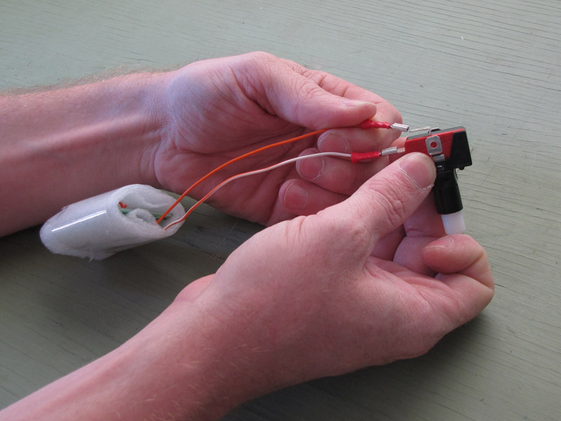
Attach the quick-connects to the appropriate terminals on the switch.

Bend the quick-connects up at about an 80-degree angle, as shown. This will make it easier to fit the switch assembly down in the cup.

Install PCB in cup

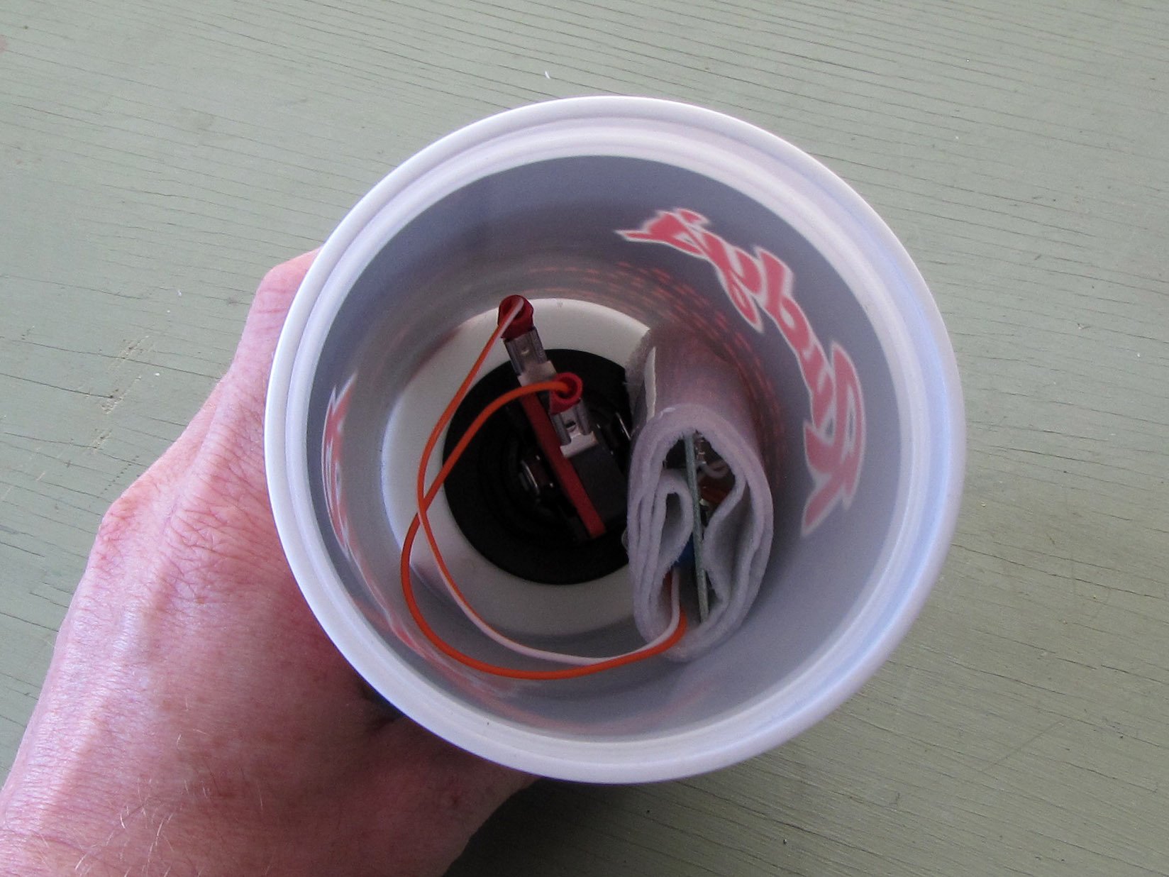
Put the switch with the PCB leads attached back into the cup.

Insert the switch back into the mounted button housing and twist it clockwise to lock it in place.

Adjust the position of the PCB “bundle” inside the cup so that the PCB is as close to the bottom of the cup as possible.

Finishing touches

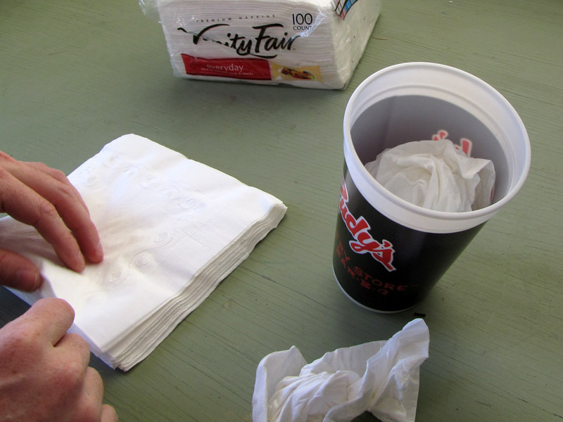
Wad a couple of napkins and stuff them into the cup on top of the electronics.

Snap on the soda lid.

Poke a straw through the straw hole and down one side of the cup.

Use it!

Put the cup in your cupholder. The button should rest against the bottom of the cupholder, but it should not be heavy enough to activate the button under its own weight.

To open or close the garage door, just push down on the top of the cup.

Alternately, if your cupholder is too narrow to allow you to push the button in place, you can just pick the cup up and bump the button against the center console.

I wired up the LED in the pushbutton to show off what was going on in the photograph, but there is no practical need for you to do so. I added an additional 9V battery in the cup to power the light.