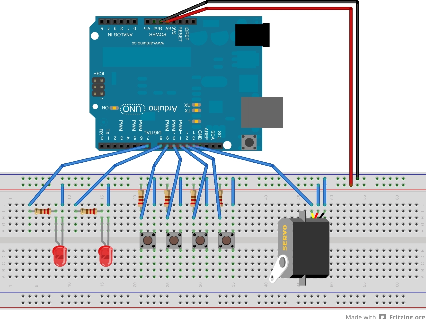
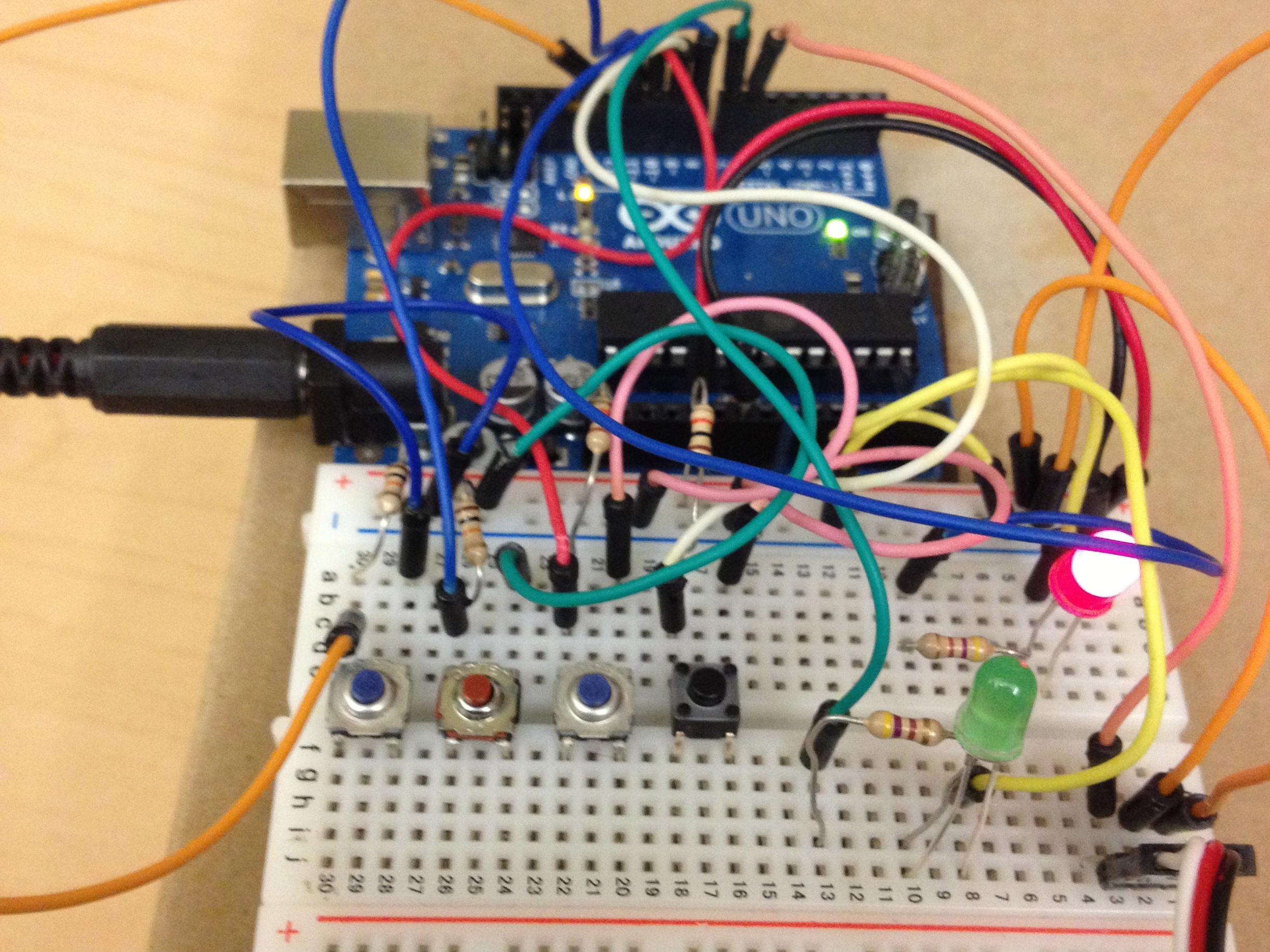
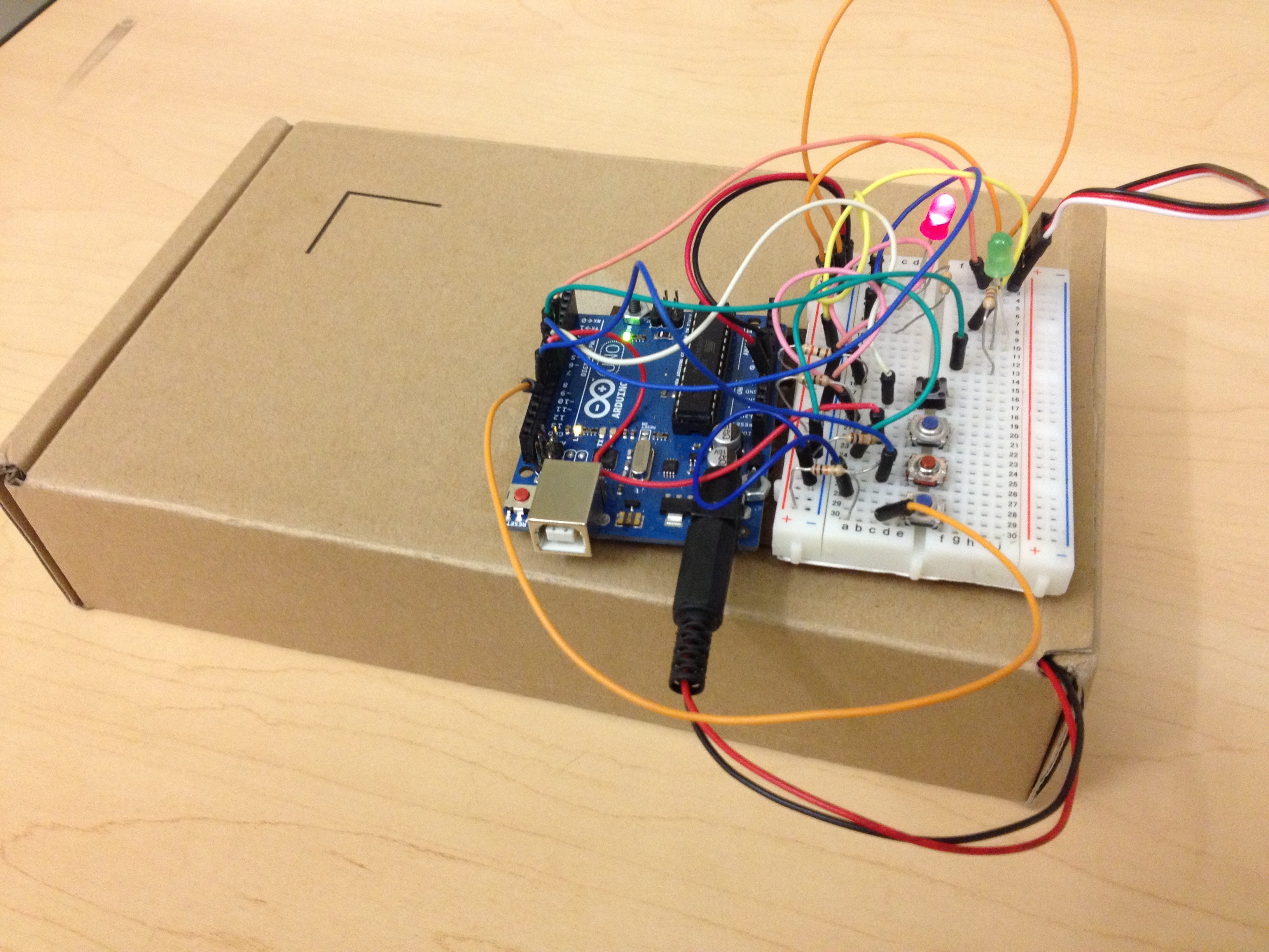
Note: Columns are vertical in the first picture (perpendicular to the indent) and rows are horizontal in the first picture (parallel to the indent). Blue/Black/Negative is for ground. Red/Positive is for the power, 5V.
Place the pushbuttons so that each one is straddling the indent in the middle of your breadboard. (Buttons will only go into the holes if they’re in the proper orientation.)
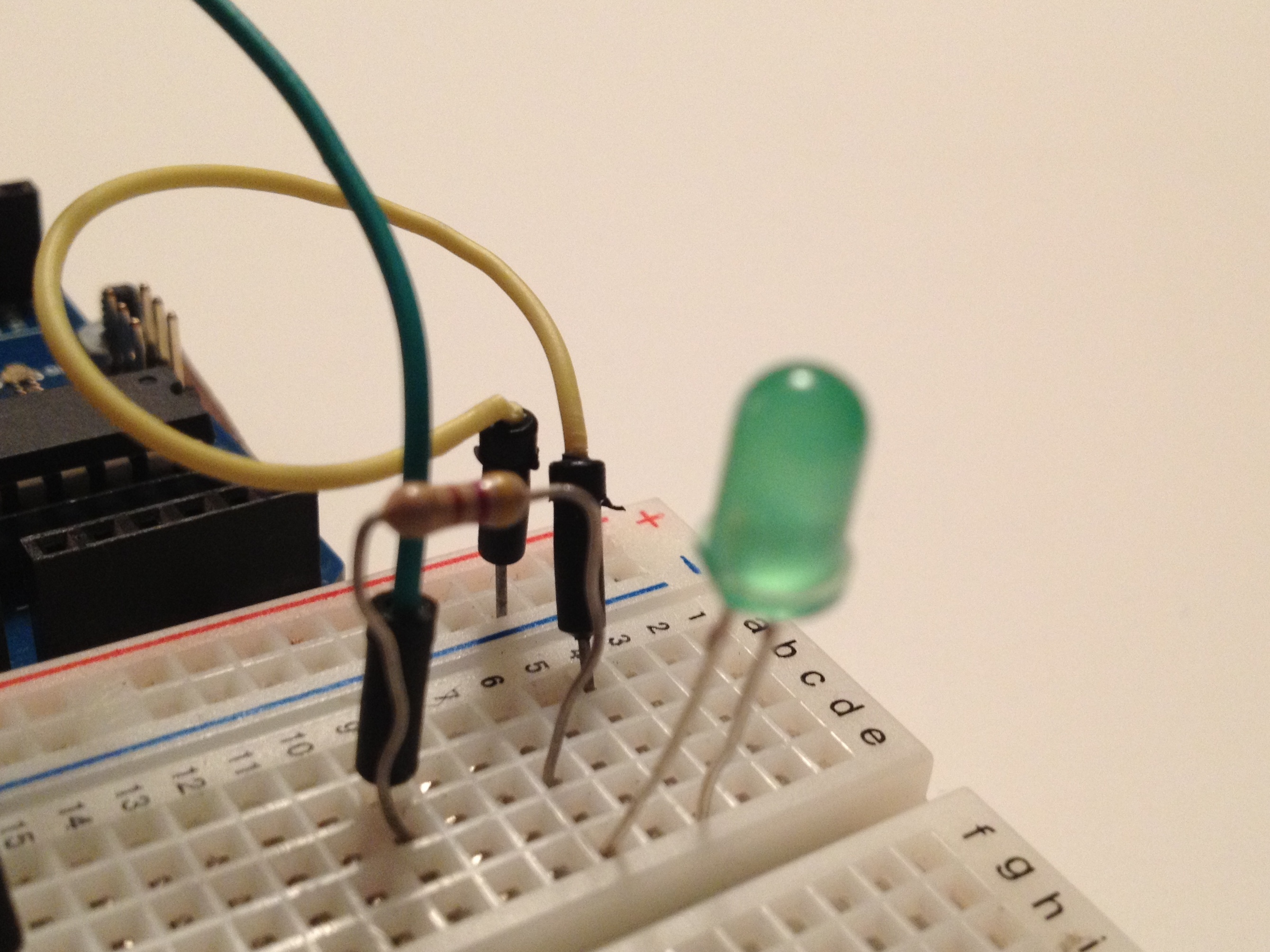
Put one lead of a 10KΩ resistor in the same column as one left prong of the button, and put the other lead of the resistor on the red row along the edge. Repeat for each button.
Between the resistor and the left button prong, in the same column, put a jumper wire going to the pin on the Arduino you want to connect that button to. Repeat for each button. (Use pins 12, 11, 10, and 9 respectively).
Put one end of a jumper wire in the same column as the right button prong, and the other end in the blue row along the edge. Repeat for each button.
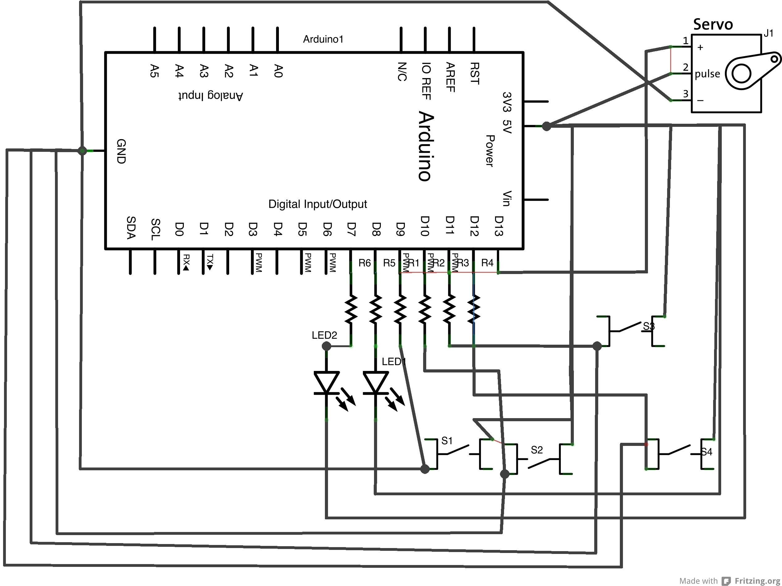
(I apologize for the messy circuit diagram, I had some trouble with fritzing).