With this SIM Card Reader and Writer kit, you are free to experiment with your SIM cards and the information that is stored on them! You can back up stored SIM card data, recover deleted SMS’s and phone contacts, and even examine the last 10 phone numbers dialed!
Projects from Make: Magazine
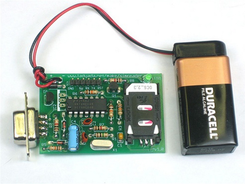
SIM Card Reader/Writer Kit
It's easy to assemble the SIM Card Reader/Writer kit; this guide walks you through the process step-by-step.