This article appears in Make: Vol. 76. Subscribe today for more great projects and tutorials.

The Ball Drone Project Mk II is a great way to get into single-rotor drone experimentation. It’s an extraordinary drone design, totally different from the widespread multirotor aircraft — lets you really think outside the box. 

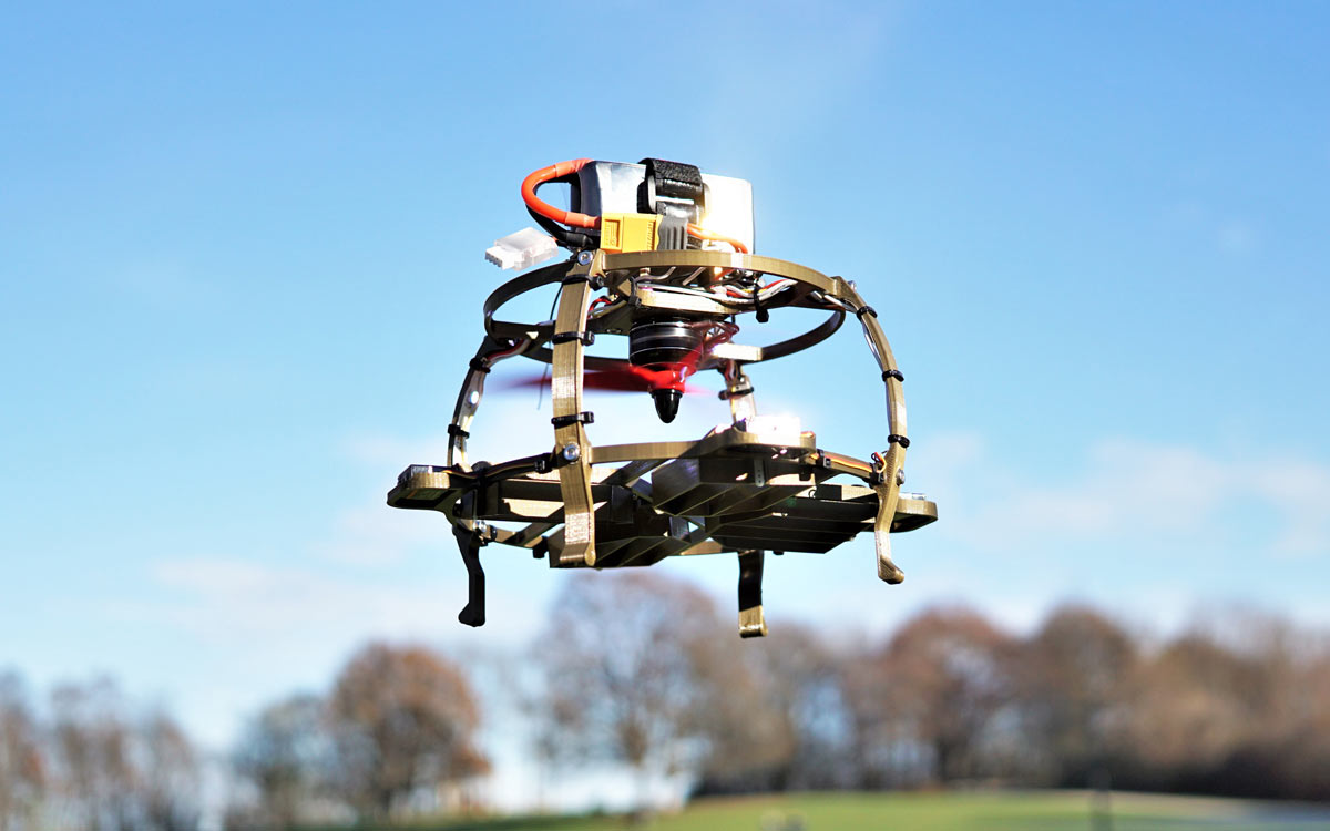
This project shows a complete 3D-designed and -printed single-rotor drone. The self-made, 7″-round aircraft flies with a single rotor and steers with thrust-vectoring vanes. It uses common R/C components like radio receiver, LiPo battery, ESC, brushless motor, propeller, and servos. In addition, the commercial flight controller runs Betaflight, a popular free software option for drone racing. 

Figure A

Take a closer look at the four thrust vectoring vanes to fully understand how this thing is working. Four mini servos twist these vanes to direct the thrust, totally unlike your normal multi-rotor drone. It’s a great learning experience and will surely generate excitement when you show it off to noobs and experienced drone pilots alike (Figure A).

I first published this project on Hackaday.io, as a complete remake of my earlier ball-drone project. The first version proved the concept, but I made it just too hard, building and programming my own controller from scratch. This new version is still a somewhat advanced project — skills (and tools) are needed in 3D printing, soldering, programming, and even drone flying — but this time it uses off-the-shelf R/C components and proven flight software that’s free. 

Anyone can build this Ball Drone. Learning to fly it is a whole new challenge!

What will the next generation of Make: look like? We’re inviting you to shape the future by investing in Make:. By becoming an investor, you help decide what’s next. The future of Make: is in your hands. Learn More.

Project Steps

Build Your Ball Drone

1. Get your parts ready

Figure B

3D print all the parts from thingiverse.com/thing:4635873 (Figure B) and clean them up: maybe you had some stringing, or maybe you used supports for the drill holes. I printed the drone in PLA, but I’d use PETG in the future because of its strength. The construction is designed for a layer height of 0.2mm and a nozzle diameter of 0.4mm. Support is not required.

Add the servos to the lower ring

Mount each servo in its bracket in the lower ring, so that its axis of rotation is aligned with the center of the drone.

Center the servos

Center each servomotor’s rotor position by sending it a 1.5ms pulse. For example, you can do this with a simple Arduino sketch that calls the Servo library (arduino.cc/reference/en/libraries/servo). Once the servo is centered, mount the servo horn that comes with the ES9051 servomotors.

Insert the vanes and bolts

Figure D

Assemble one vane at a time. The servo horn fits exactly into the fitting on the vane wing. I used M3×12mm screws to make a positioning screw on the opposite side (Figure C). When all 4 wings are mounted, the lower ring is ready and can be put aside for a moment (Figure D).

Add the motor on the upper ring

Figure E

Mount the brushless motor first. Add screws for the flight controller from underneath so that the flight controller can be pushed down over the threads (Figure E). Then fix the flight controller in place using M3 circuit board spacers.

Add the legs

Add one drone leg after the other using M3×10mm screws with washers and nuts on the inside. Your drone should now stand on its own feet and look very similar to the final design

Connect the electronics

Figure F

Figure G

Now it’s a good time to solder up the ESC as well as the R/C receiver (Figure F). Depending on your battery connection, you can also solder “an XT60 plug to the supply from the ESC, as well as two small cables to supply your flight controller. I attached (daisy-chained) WS2812B lights on the inside of the drone legs and used these to connect the servo power lines (Figure G). The signal lines of the servos must be extended to reach the flight controller in the middle of the drone.

Figure H

Next, solder the LED strip, the motor, and the servo lines to your flight controller (Figure H). If your flight controller does not have any direct servo outputs, it is certainly possible to relocate these to the current motor connections via a “resource remapping” in Betaflight (see Step 8).

Figure I

Figure J

After you’ve soldered all the cables to your flight controller, you can screw the battery holder onto the spacer, and thread a battery strap through (Figures I and J). Assembly is done!

Configure the Betaflight software

Contrary to my previous ball drone, this time I wanted to use a flight controller and software that are freely accessible to virtually everyone. There are a lot of open source projects, but Betaflight is currently the standard for racing drones (github.com/betaflight/betaflight). There are many tutorials and resources on the internet so I won’t explain Betaflight here. What we need to know is: How do you get from a racing quad to a single-rotor drone? Here’s how:

Resource mapping: To control your single-rotor copter, you need one motor and four servos. Most flight controllers can run four motors and some of them have servo outputs as well. So what I did is remap my servo controls to Betaflight’s standard four motor outputs. But then I needed a connection for my motor. In the configuration for the Fury F4 flight controller I used (github.com/betaflight/betaflight/tree/master/src/main/target/FURYF4), I was able to see at which pins’ timers are available. You often read about using the LED_strip port for a motor, but I wanted to use the LED_strip port for LEDs, so I decided to remap the PPM input pin as my motor output. To learn more about resource remapping and how to do it, watch Joshua Bardwell’s video at youtu.be/gL1DxUFjFq8.

The CLI commands I used:

resource MOTOR 1 NONE
resource MOTOR 2 NONE
resource MOTOR 3 NONE
resource MOTOR 4 NONE
resource PPM1 NONE
resource SERVO 1 A03
resource SERVO 2 B01
resource SERVO 3 B00
resource SERVO 4 A02
resource MOTOR 1 C09
save

Figure K

Mixer configuration: Next, the flight controller must send the correct signals to the motor and servos. For this, you’ll adjust the mixer. Under the Configuration tab, select Custom Airplane in the Mixer section (Figure K). Handle this via the command line:

# smix script for singlecopter on
MambaF405_MK2 (by Benjamin Prescher)
mixer CUSTOMAIRPLANE

# load a standard motor mix
mmix reset
mmix load airplane # Motor1 as ESC output
# mmix 0  1.000  0.000  0.000  0.000

# smix
smix reset
smix 0 3 0  100 0 0 100 0
smix 1 2 0 -100 0 0 100 0
smix 2 4 1  100 0 0 100 0
smix 3 5 1 -100 0 0 100 0
smix 4 3 2 50 0 0 100 0
smix 5 2 2 50 0 0 100 0
smix 6 4 2 50 0 0 100 0
smix 7 5 2 50 0 0 100 0
save

If you want to find out more about what’s actually happening here, take a look at the Betaflight docs at github.com/martinbudden/betaflight/blob/master/docs/Mixer.md.

Stabilize the drone with servo PIDs

As you can see in Figure K, I have set a relatively low PID loop rate of 1kHz. The servos I’m using can usually be operated with a maximum servo_pwm_rate about 333Hz (there are also servos that can certainly handle more). I’ve set my servo_pwm_rate to 250Hz, which corresponds to one-quarter of the PID loop rate. As far as I understand the algorithms in Betaflight, there’s no point in setting the PID rate artificially high if the command for the actuators can only be updated at a fraction of that rate anyway.

Figure L

I use strong P values (Figure L), which tend to make the vane servos “jitter.” Betaflight has a great feature to solve the problem — a servo low pass filter. Handle this via the command line:

set servo_lowpass_hz = 20
set servo_pwm_rate = 250
save

For more on tweaking the PIDs, be sure to read my latest logs at Hackaday.io.

Solo Flight

u’ve set up the drone, connected everything, and implemented the configuration, test it out. Your drone should behave as follows:

  • Transmitter roll right — forward and rear vanes move right
  • Transmitter pitch forward — left and right vanes move forward
  • Transmitter yaw right — forward vane moves left, right vane moves forward, rear vane moves right, left vane moves back

You’re now flying a unique single-rotor, thrust-vectored drone that’s ripe for experimenting. I would love to see what you do with it.

Conclusion

Betaflight is just one option I used to get this drone in the air. All of the above steps can be done using iNav as well (though I haven’t tested it), and I’ve heard that Ardupilot should do the job too! Try using a GPS with iNav for more flight features that aren’t supported by Betaflight for now (such as altitude and position hold). Have fun!

Leave a like or follow at hackaday.io/project/175512, and share your makes at thingiverse.com.