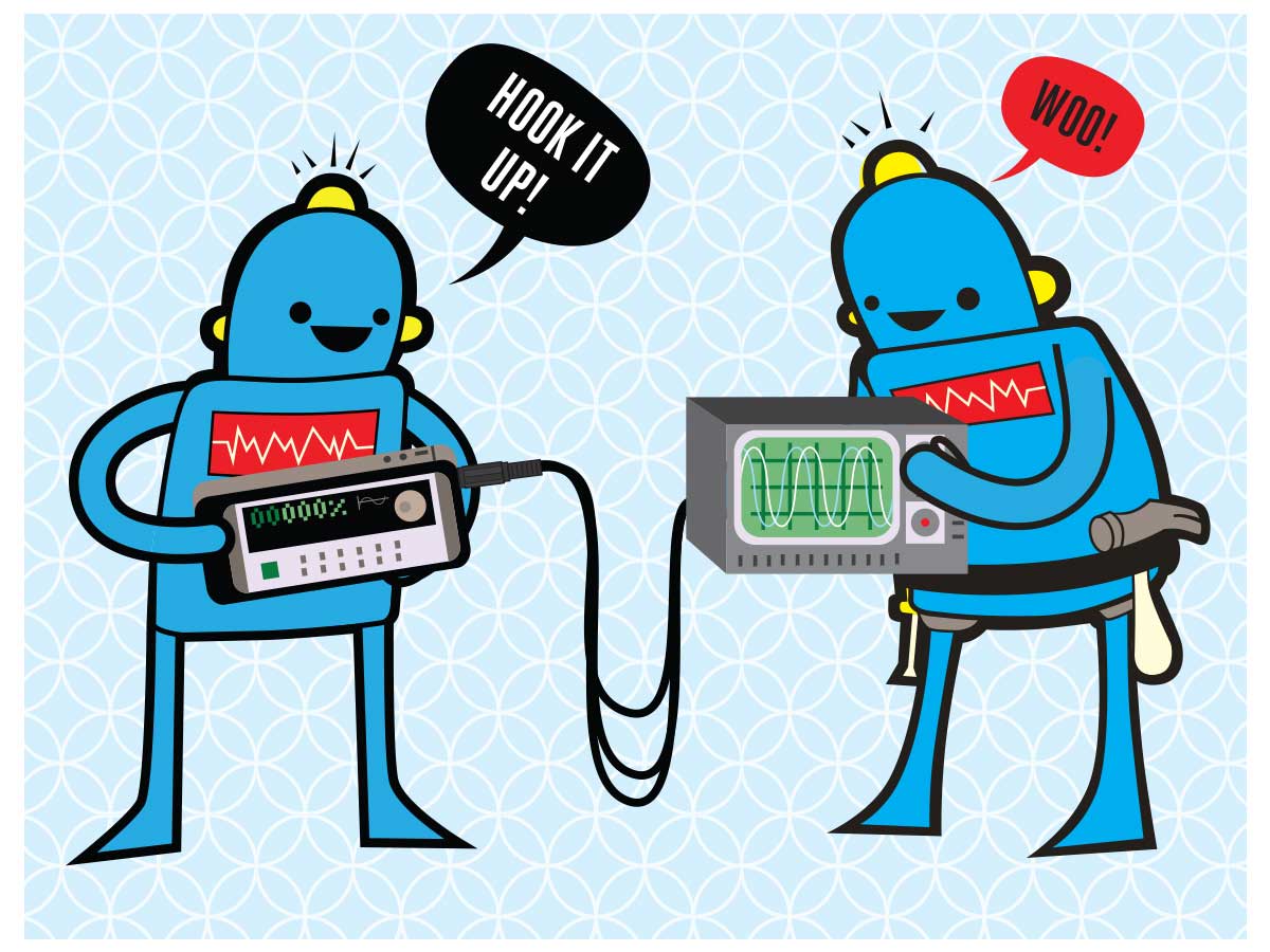
A signal generator is handy to have around the lab. It’s perfect for testing inputs on a new hardware design; use it with an oscilloscope to verify the behavior of your circuit. Turn a smartphone into one for less than $15!
Projects from Make: Magazine
Smartphone Signal Generator

Wire the adapter.

Unscrew the cap from the 3.5mm plug. Strip 1/4″ of insulation off the ends of each wire. Solder one wire to the plug’s large tab first — this will be the ground.
Then solder each of the other wires to the smaller channel tabs — these will be the signal wires. Replace the cap.
Either solder or screw the opposite end of the ground wire to the black alligator clip. Then connect the 2 red alligator clips to the signal wires. Make sure the alligator clip insulator is slid down the wire beforehand so they can be replaced after soldering.
Download signal generator app.

Download the appropriate signal generator app for your device. On iOS, Sig Gen is one option. On Android, Waveform Generator is a great app to use.
These apps will generate various waveforms at different frequencies and amplitudes. They range in price from free to a couple dollars.
Connect adapter to smartphone.

Plug the adapter into the phone. Connect the clips to your oscilloscope, ground to ground and then signal to input.
Turn headphone volume to maximum. Start the application. Select the waveform, amplitude, and frequency and start generating waves!
To protect the headphone jack, a simple buffer can be added between the adapter and the circuit
Conclusion
Suggestions on how to use your signal generator
Generate a signal to test a circuit.
Now that you have the signal generator working, try building a simple low-pass filter using a 1k ohm resistor connected to a 0.1 uF capacitor that then connects to ground. Vary the frequency and watch how the signal output between the resistor and capacitor is filtered below 1500 Hz!
Test your speakers.
Try connecting it to a speaker. Adjust the signal level and the type of signal generating (square vs sine). Adjust the frequency. Do you notice any differences? If you want to increase the output to the speaker (gain) adjust the resistor value in the op-amp protection circuit so that the gain is no longer one (unity).
Generate audio tones.
Try generating different frequency tones. What is the minimum frequency you are able to generate? What is the maximum? At what point can you no longer hear the audio being generated?
Troubleshoot a malfunctioning circuit or device.
Try troubleshooting a malfunctioning circuit or device. Disconnect the input of the circuit and connect the signal generator instead. Setup the generator to output the type of signal, frequency and signal level that would normally be input to the device. Now start debugging!
Experiment with a circuit. (signal into an op amp for gain and frequency response measurements)
Try building a high and low pass filter using an op-amp. You can sweep through the different frequencies and record the voltage output every 1 KHz. If you plot the data how does the response look?
For an example of a circuit, visit makezine.com/go/buffercircuit.
This project first appeared in MAKE Volume 36, page 115.


