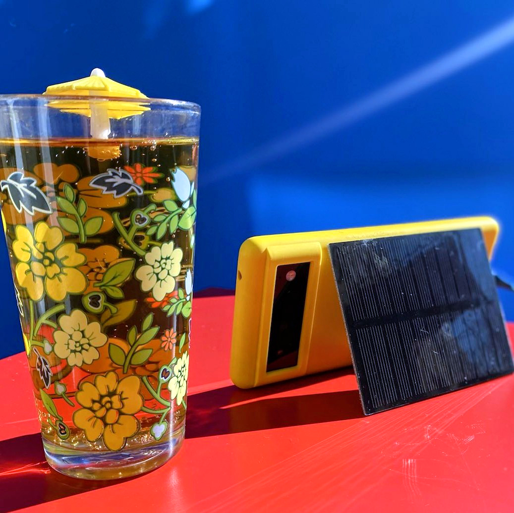
It’s fun to use mini solar cells to charge your gear or power small gadgets, and once you’ve learned the basics you can scale up to bigger panels. Let’s explore ways you can harness solar energy for your own DIY projects — mobile, wearable, or otherwise — and say goodbye to (some) batteries and plugging things in!
Early Solar Energy
While the first solar electric panel is credited to Bell Labs in 1954, there have been a variety of other solar-powered devices for hundreds of years. The cell produced by Bell chemist Calvin Fuller and physicists Daryl Chapin and Gerald Pearson was the first silicon solar cell, following their success with semiconductors in 1947.


Solar heat energy has also been used in a variety of ways, including architect Eleanor Raymond and MIT engineer Maria Telkes’s Dover Sun House in 1948 (Figure A
Of course, solar energy goes way back to ancient civilizations using sunshine to dehydrate foods, using magnifying lenses to light fires, using reflection and positioning to tell the time or light a room, among other uses. When we think of it like that, contemporary solar cells are just a single point on a long continuum of solar possibilities!
Photovoltaic Phenomena
Solar panels utilize what we call the photovoltaic effect — the ability of a material to emit electrons when exposed to light — to produce electricity. This effect was observed as early as 1839 by French physicist Alexandre-Edmond Becquerel, who discovered that metal electrodes in an electrolyte solution produced a current when exposed to solar radiation. Although at the time he couldn’t explain it, it lay the foundation for what was to come.

Today many solar cells are made primarily of silicon (Figure 
a material that partially conducts electricity, but also has some of the properties of insulating materials that don’t conduct.
A Single Cell
A solar panel like you might see on someone’s roof is made up of many individual solar cells that are wired together. Each solar cell works by converting the sunlight hitting the semiconductor into electricity. The energy from the light (photons) is absorbed into the panel, which knocks electrons loose in the cell.

Each cell is designed with positively (p-type) and negatively (n-type) charged semiconductors in a sandwich, which creates an electric field that forces the drifting electrons to flow toward conductive metal plates on the outer layers of the cell, and then through wires like any other source of electricity (Figure C
A Solar Panel
Much like other electrical circuits, individual solar cells can be wired in series or in parallel to modify the amount of voltage and current produced by the panel. Often, cells may be arranged in a combination of both to create the desired parameters. In a parallel circuit, current (amperage) increases and voltage remains the same. In a series circuit, voltage increases and current remains the same. In Figure D

Many solar cells are often sealed into a single panel that has a wattage and voltage rating. Wattage is the power produced or used per second. For example, a 60-watt light bulb uses 60 joules of power per second. You can calculate the wattage of a circuit you want to power by multiplying volts by amps, for example in a 3 volt, 0.33 amp LED:
W = V × A
W = 3 × 0.33
So this is a 1-watt LED.
Power over time is measured in watt-hours, which is watts × hours. To get an idea of how much power you might need to power your home for a whole day, you can check your power bill, which is often measured in kilowatt hours (kWh). The average household uses 20–30kWh a day; today I’m slightly embarrassed to admit I used 43 somehow.
Let’s say we got a new 250-watt panel. To determine the capacity of our setup, we will multiply panel watts × average hours of sunlight × 75% (as it is unlikely to be at full efficiency):
250 watts × 5 hours × 0.75 efficiency
= 937.5 daily watt-hours.
And then convert it to kWh like our electricity bill:
937.5 / 1000
= ~0.94kWh per solar panel.

Your panel will usually tell you its voltage output, but that indicates the performance of the panel in ideal conditions. A great exercise is to take your panel outside, connect a multimeter to the panel’s positive and negative leads, and turn the meter to the voltage reading setting. As you
move the panel, you can clearly see how the voltage output is being affected (Figure E
You can do the same thing to see the amperage output of a panel.
Most solar panels have no amperage rating. Your circuit will draw current measured in amps (or milliamps, depending on the scale of your circuit). The consumption of amperage over time is measured in amp-hours (or milliamp hours). You’ll typically see this on batteries which have an Ah or mAh rating, so you may be familiar with the concept. Why is this important? Because most solar circuits, as we’ll see below, use a controller to charge the battery while the circuit draws power from the battery, instead of the panel directly powering the circuit. So you’ll want to calculate the draw of your circuit, and then find a battery that charges faster than your circuit discharges it.
Again, it’s important to remember that your solar panel output is charging your battery, and it’s your battery output that has to match your circuit requirements. For example, if my battery has 500 milliamp hours, and my LED draws 20 milliamps, my battery will last for 25 hours at full brightness:
Battery capacity (mAh) / Current draw (mA)
500 / 20 = 25 hours
Don’t forget to make sure you’re always working in the same units, and convert if needed by moving the decimal point.

You can connect a solar panel directly to the power and ground wire of any simple electronic component to power it with the right voltage (Figure F
Solar Toolbox
After you’ve decided what exactly you want to power, you’ll need to find a solar panel. They come in all sizes, but I’m going to focus on simple electronics rather than powering your home, RV, or boat.

Adafruit sells a wide variety of panels, from a tiny 5V 40mA badge, #700 (Figure G

In addition to the solar panel specs, it’s a good idea to keep an eye on the connectors it comes with: either barrel jack, JST, or USB, depending on your use. There’s nothing worse than getting all the parts for a project and winding up with the wrong connectors.

If you’re looking for something smaller, I also love Osram’s tiny, 1/8″ BPW-34 through-hole solar cells (Solarbotics #SCPD, Figure I


After you’ve chosen a panel, you’ll want to pick a battery and a controller board. My favorite is the SparkFun Sunny Buddy solar charging board, #12885 (Figure K

If your battery outputs 3.7V but you want to build something like a solar-powered Raspberry Pi which requires 5V, you may want to use one of Adafruit’s PowerBoost boards, #1903, to power your project (Figure L).

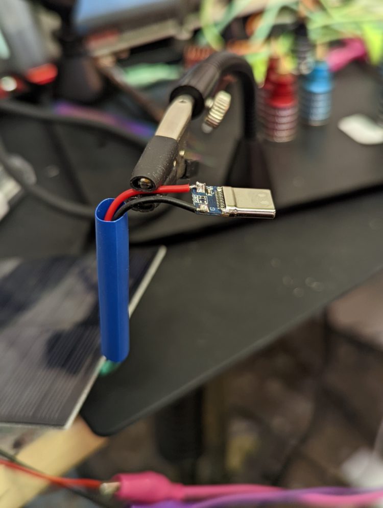
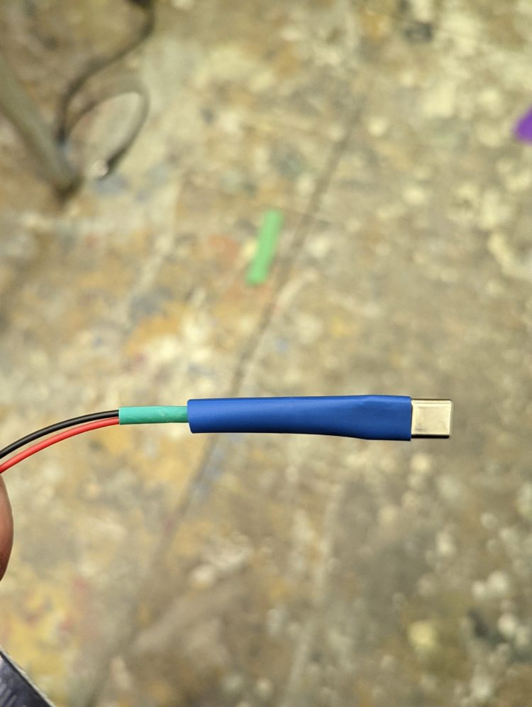
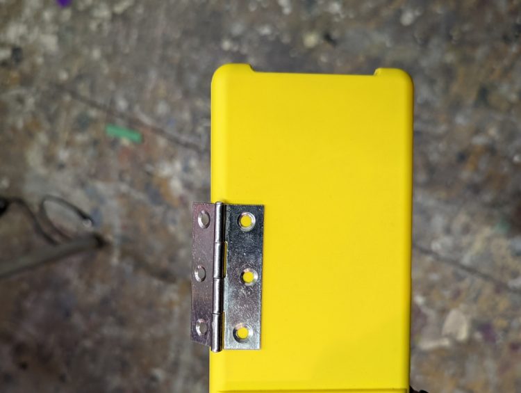
In this tutorial, I’ll show you how to connect a solar panel to your phone so that you never run out of power. There are lots of variations of this circuit, so make sure to verify your phone’s capabilities and ports, and your solar panel specs, before beginning.


