At BEAM and other robotics competitions, builders pit Solarrollers against each other in a kind of robo-mechanical Pinewood Derby.
Projects from Make: Magazine
Solarroller BEAM Race Car
A little solar-powered racecar made from techno-junk.
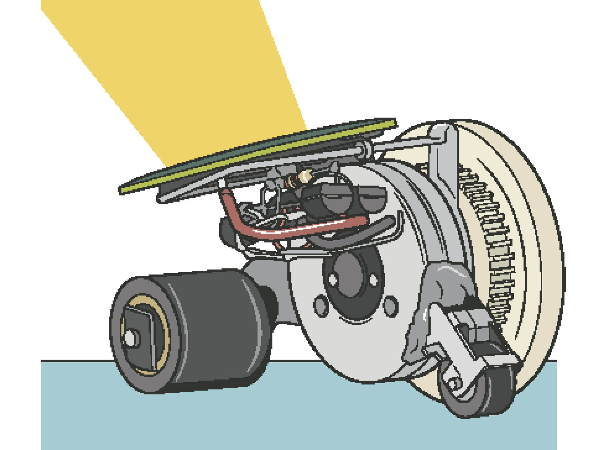
A little solar-powered racecar made from techno-junk.

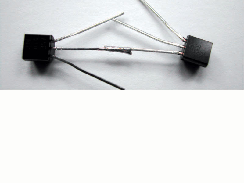
We’ll be freeforming this circuit, which means connecting components together directly, without a board. Normally I’d breadboard and test my circuits before soldering, but this one is so simple and has so few parts that we can live dangerously. Parts are easily desoldered and resoldered if there’s a problem.
Face the two transistors up with their pins toward each other. Solder the base pin (middle) of the 3904 transistor to the collector pin of the 3906 (the right pin, as you read the printing).
Use needlenose pliers to gently bend the 3904 emitter pin (left) 90 degrees to the side and its collector (right) 90 degrees up. Bend the 3906 base pin (middle) 90 degrees up and its emitter (left) 90 degrees to the side. Solder the 2.2k resistor from the 3904 collector to the 3906 base.
Trim excess lead length from previous step. Place the 1381 voltage trigger to the right of the 3906, facing the same way. Solder its Pin 3 (right) to the 3904 emitter and its Pin 1 (left) to the 3906 collector. Finally, arc its Pin 2 (middle) around and solder it to the 3906 emitter (left). There’s your basic circuit, ready for motor and power!
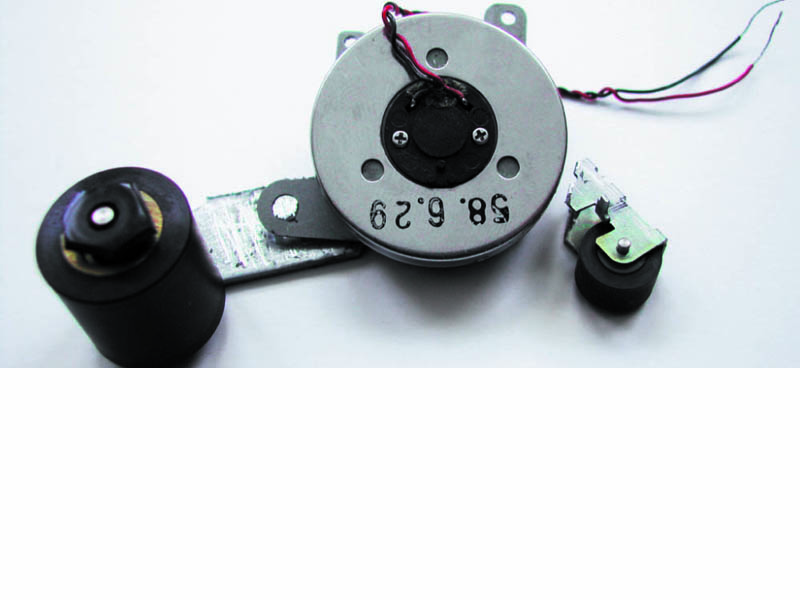
Solarroller builders have used all sorts of materials, from Lego bricks to soldered paper clips to computer mouse cases. This popular approach relies on parts from an old cassette player and VCR. Your mileage may vary, depending on the parts that you use for the body and drivetrain.
Cut the arms on the two pinch rollers with a Dremel and cut-off wheel, so that they make full, flat contact against the motor casing. The Solarroller will stand on the triangular base that’s formed by these two idler wheels and the larger drive wheel that will go onto the motor’s drive shaft.

Prepare the drive wheel. First, check that it will fit on the motor’s drive shaft. (The hole in the hub of the disc I used was too small, so I reamed it out using a Dremel router bit.)
Then glue a rubber band around the outside of the wheel, to improve traction. Cut the band, smear a thin layer of glue onto one side, and when it gets tacky, carefully roll the wheel over this “tire” until it comes full circle.
Let the join overlap, then use a hobby knife to cut away excess rubber and make sure the ends are perfectly joined.
Epoxy the two idler wheel arms into position on the motor casing, then fit the drive wheel onto the motor shaft without gluing it (use poster putty to hold it on, if needed).
It is critical that all three wheels run parallel to each other and make full contact with flat ground when the Solarroller is standing.
If your cassette motor has mounting tabs like ours, you can affix the larger roller arm to the motor’s large tab, pointing toward what will be the front, and leave the two other mounting tabs and holes pointing up on top, for attaching the circuit and solar panel.
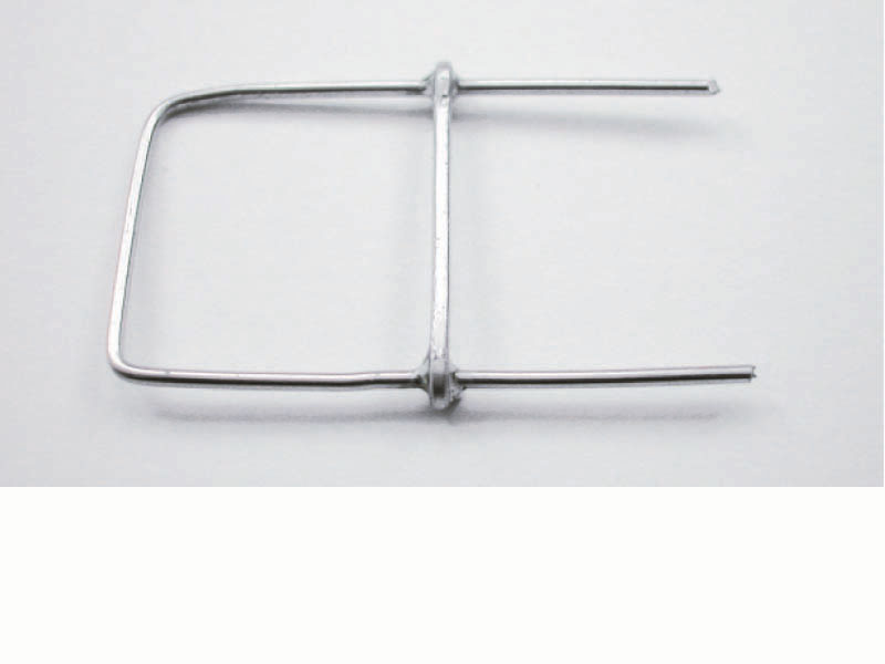
Cut about 4″ of wire from a large paper clip and fashion it into a U shape. For a cassette motor with tabs, it can be just wide enough to run between the two upper mounting holes.
Trim the remaining piece of paper-clip wire and solder it across the U as a cross-brace, about ¾” from the open end.
Epoxy a capacitor directly to the motor casing, running horizontally, on the side opposite the drive wheel. The leads should point backward, with the cathode (-) closer to the motor.
Solder (or epoxy) the paper-clip frame atop the motor casing, using the two mounting holes if present. Since we didn’t glue the drive wheel on yet, you can remove it to access the top of the motor.
For extra sturdiness, you can position the frame so the cross-brace rests on the capacitor, and epoxy the brace onto the cap. Glue on the drive wheel.
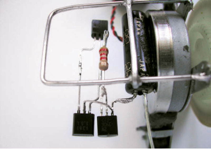
Position the Solarengine circuit underneath the paper-clip frame, next to the cap, on the side opposite the motor. Solder the 3906 emitter (left) pin to the positive/anode lead of the capacitor. The connection should be short enough so that the cap holds that end of the circuit up in the air.
Turn the Solarengine upside down and solder a scrap component lead to the 3904 emitter pin at the point where it attaches to the 1381 trigger’s Pin 3.
Bend the capacitor’s negative/cathode lead around the undercarriage side of the cap’s barrel, and solder it to the lead you just connected to the 3904. This will anchor the other end of the circuit.
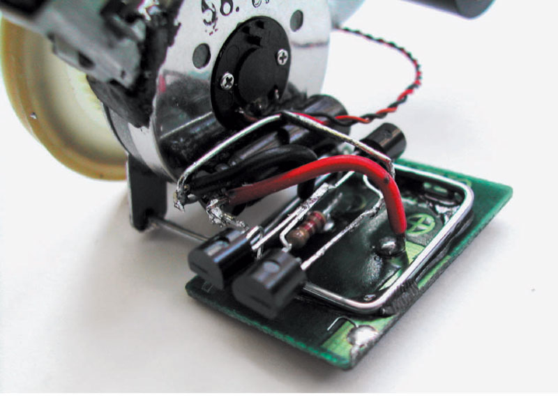
If your solar cell doesn’t have wires, attach some to the pads marked (+) and (-). The wires only need to be long enough to reach the pins on the capacitor. Thread the solar cell’s wires through the frame and epoxy the cell to the top. When the epoxy is set, solder the solar cell’s positive to the cap’s positive/anode and the cell’s negative to the cap’s negative/cathode.
Finally, connect the motor. Solder the positive/red motor wire onto the 3906 emitter (left) pin and the negative/black wire to the 3904 collector.
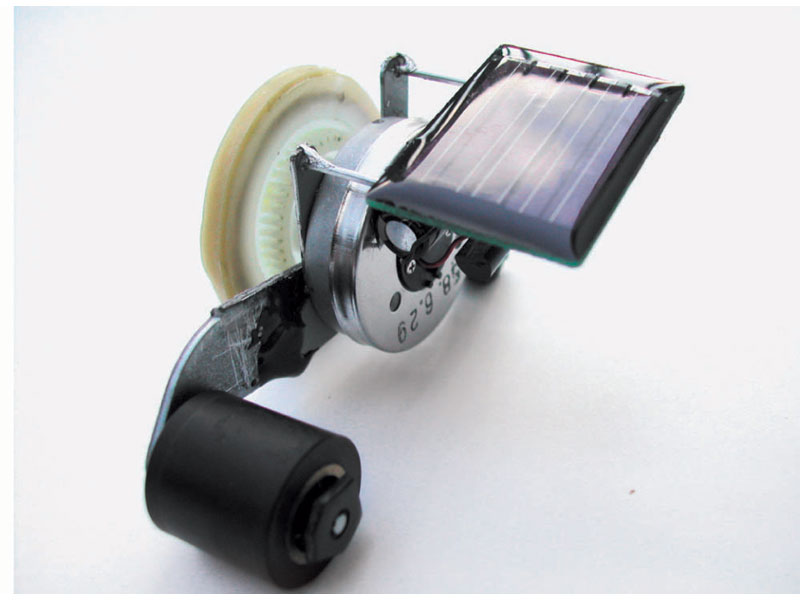
Now, put the Solarroller on a flat surface in the sun, or shine a flashlight on the cell. After a little while, the circuit will trigger, the capacitor will dump, and your Solarroller will take off for a short run. Shine, wait, and repeat.
If your BEAMbot doesn’t make you beam, carefully examine all connections, resolder anything that looks weak, and separate any components that might be touching (shorting). It’s a simple circuit, so not much can go wrong besides incorrect connections or bad joins.
There are many more hacks and variations on this project as well as other applications for the Solarengine. For more information, see “Getting Started in BEAM,” MAKE, Volume 06, page 57. Schematic for Miller variant of Solarengine circuit: www.make-digital.com/make/vol06
Try Andrew Miller’s more efficient variant of the basic Solarengine, which is almost as easy to build. You need a different resistor, an additional capacitor, and a diode, but you can lose the 3906 transistor. Varying the value of the small cap, between 0.47µF and 47µF, lets you “program” different discharge times. (See schematic at: www.make-digital.com/make/vol06.)