An oscilloscope, or o-scope, is the best friend of an electronics enthusiast, be they professional or hobbyist. While a digital multimeter can help you measure steady state and RMS (Root-Mean-Square) voltages, theoscilloscope can not only measure peak-to-peak voltages, but more importantly provide timing information on your signal.
For instance, have you ever been working with an Arduino controlling a servo motor that has to have just the right pulse width modulation in order to spin clockwise instead of counter-clockwise? During your programming, you may have wondered just how close the pulse width was to what was needed. With an oscilloscope you can measure these pulses. When dealing with analog signals, you can use an oscilloscope to see how close you are to the frequency you need or measure what frequency you need to filter. With so many digital electronic projects, timing between signals is extremely important. Therefore, having an oscilloscope is essential.
However, price can be an obstacle. Entry-level scopes can start off at a few hundred dollars. From there, higher-end scopes can end up into the tens of thousands. However, did you know that you probably have all you need to make your own oscilloscope? In fact, you are probably reading this on a device that has the essential parts needed. All other parts are probably in your parts bin.
In essence, an oscilloscope is a data acquisition box that records the voltage from your circuit. Another device on your computer already does this: the sound card. The main differences are the level of voltage each can handle, and how fast they sample the voltage (more on that later). Since the sound card on your computer can only handle a small amount of voltage (around +/- .6V to .8V) you need to scale it down. Building your own scope probes accomplishes: allowing input of higher voltages and scaling the voltage down so the sound card can handle it.
The steps below outline how to build such a probe. The probe being built here is used with the line input of a sound card. Line inputs typically accept stereo inputs, therefore this probe will have two channels. If you’re thinking of using the mic input on your system, you will want to build just one channel as mic inputs typically are mono. After the build, I’ll show you some comparisons of this oscilloscope to a lab-grade model and discuss some limitations.
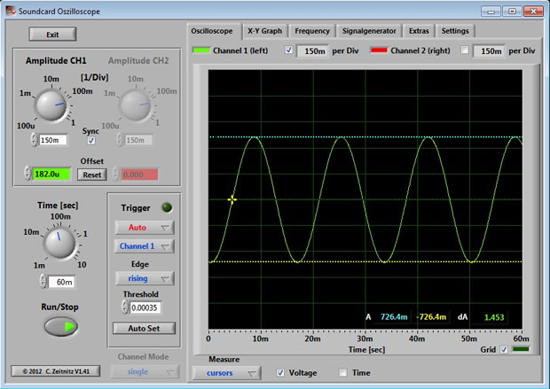
Much of this project is adapted from http://homediyelectronics.com/projects/howtomakeafreesoundcardpcoscilloscope, and the software can be found http://www.zeitnitz.de/Christian/scope_en.
all right this is great im gonna do this for sure!!! for basic electronics this should work!!
and being small i bet this will fit in an altoids tin!!
nice make to night
can do you do a video on midi and the 1 – 16 midi channels and now to use with arduino im suck on it and ther no note of the codes out ther
If you just use the midi or usbMidi libraries, it’s pretty simple:
Midi.sendNoteOn(note, velocity, channel);
Midi.sendNoteOff(note, velocity, channel);
So say you want to send a middle C (60) at full velocity (127), you would use midi.sendNoteOn(60, 127, 0); then send a note off depending on when you want to silence the note. The third parameter is up to you, I usually just use 0.
If you’re using MIDI over USB rather than going through a midi interface or a midi DIN, just change midi.sendNoteOn(…) To usbMidi.sendNoteOn(…)
The idea is nice, but the circuit’s simplicity has one major drawback: its performance depends on the input impedance of the sound card. A ‘scope should not present an excessive load to the circuit under test, which is why ‘scope inputs are standardized at 1 megaohm impedance. With the pot turned way down, e.g. at 10%, this circuit comes close. But when you turn the pot all the way up, the input impedance is essentially the input impedance of the sound card which is likely to be at least an order of magnitude lower (100k ohm or so). In some circuits, this will cause measurement errors.
The obvious solution would be to add unity gain buffers between the pot wiper and the soundcard input, but this requires a power supply. That said, a TL062 and a 9V battery would probably suffice.
The first useful ratshack project I’ve seen so far. Nice!
can i use http://www.ebay.co.uk/itm/200914593086?var=500154612807 or will one in the uk
I think you will find Visual Analyser by Sillanumsoft to be more useful software. http://www.sillanumsoft.org/
Hi everyone. I’m the author of the article upon which this is based as acknowledged by Ryan above. You might like to know that I also wrote a book showing you how to build a better probe together with a useful calibrator and signal generator. The book is available from Amazon Kindle here http://homediyelectronics.com/amazon/sco
What is the actual component name of the ossiloscope clip lead? I tried searching for “ossiloscope clip lead” in Element 14, I cannot seem to find it.
Hi Jason,
They are called miniature probe clips amongst other things. There is a link to the product on Amazon in my parts list for the book version of the oscilloscope here: http://homediyelectronics.com/books/soundcardoscilloscope/parts-list.php
Hi, I have been planning on building one of these now for months and have yet to put solder to wire, but it is indeed going to happen soon. I found a cheap USB sound card that I think I will use instead of endangering my laptop. I have also played with the idea of using an old broken tablet, and soldering directly to the motherboard, then having a portable unit that I could use in the field if needed, I see there are android programs available to use but I fear I could only use one lead then as they only have mic input but it may work anyhow. Just thoughts, thanks a million for the circuit I think it easier then the one you based it on, at least by my way of thinking.
Would this measure the clock source of the microcontroller or the 20MHz oscillator signal?
Can you install bnc’s and use standard probes with this? What would have to change to do this? I purchased pcb bnc’s and was going to use the standard probes I have that are 100mh.
Made this device, thank you. It working. But too mich noice ^( And vrey low resolution. I can see 300 baud, but no 19200, just single impulse. So sad, I need real oscilloscope ^)
Made this device, thank you. It working. But too mich noice ^( And vrey low resolution. I can see 300 baud, but no 19200, just single impulse. So sad, I need real oscilloscope. If I want to see 115200 buad signal, I must have 2M oscilloscope.
Ok, so I have a question.
This probe, for this oscilloscope, is based on a standard 44Khz Sound Card. But nowadays we have 96Khz Sound cards, and the “gimmick”? 195Khz.
So I was wondering, if a cheap-cheap 195Khz recording, external, usb card could maybe … measure as high as 120Khz, for example (that would be awesome!)?
What do you guys think?
Does anybody read these things? :O
Isn’t my question legitimate?
It’s obvious that with a higher sampling frequency audio card you will be able to measure higher frequency signals.
However “44KHz” doesn’t mean that it will be good for 44KHz signals. It means that the sound card “checks” the signal voltage 44000 times per second. So if you’d try to measure for example a 22KHz sine wave, which has two times slower frequency than the sampling rate, you will only see two points per signal period, instead of a sine-shaped signal.
If you want to check it out, take a piece of a squared paper and draw a 44 squares long single sine wave. Let’s assume that every vertical line on the paper is the point when the sample is taken. This way you have 44 samples per signal period. However when you draw a shorter sine wave (higher frequency), suddenly a whole period gets less samples. So the bigger the sampling frequency, the better the measured signal looks, however measured signal should have a much lower frequency than the sampling frequency.
Thanks.
I thought I read somewhere that sound cards also have a problem with higher frequencies than 20-something K, as they readings are weaker for some reason.
But your explanation is perfect! I appreciate it!
I use that sound card O-scope with 195 KHz sampling rate. It can comfortably study wave components up to 10 kHz (20 points per wavelength) and that’s about it. A perfect sine wave of 10 kHz will be beautifully represented, but a square wave of 10kHz actually is composed of various wave components with different frequencies (some very high) and can’t be integrally represented.
Thanks Renan.
Im half-way on my 2nd year (out of 5) of electronics and I’m looking for a cheap oscilloscope to study/Practice and do some projects.
I’m looking at 4 DIY oscilloscopes (and a 5th one Bought/DIY).
– Sound Card Oscilloscope.
– Arduino Scope (like girino).
– A Max#### Microcontroller Scope.
– A FPGA Scope project I’ve found. (really serious and hard stuff).
Man, if you need a oscilloscope for anything more serious than hobbies I would recommend buying a real o-scope. Those PC based o-scopes are no good for the price they are sold. Unless you really need FPGA consider searching for an old used analog 20-50Mhz oscilloscope on ebay. It depends on where you live but you can find those for less than 50 bucks. They might be ugly and dusty but they are great!
This is the cheapest o-scope you can find on Ebay Spain.
http://www.ebay.es/itm/antiguo-Osciloscopio-Philips-PM-3208-Dos-canales-/331801142507?hash=item4d40e3a4eb:g:AeoAAOSw1ZBUtisY
an old, old (1989) 2ch Philips scope for 104.99€ + 24.90€ shipping. (a total of 144.88$). It’s so expensive, and the scope is so old.
Now a DSO, can be bought for about 50€. Theses are the ones I found easily these 2.
A USB 20Mhz scope (like the philips above, but without the protections and with a max. input voltage of 35v). NO DISPLAY.
http://www.ebay.es/itm/Hantek-6022BE-PC-Based-USB-Digital-Storage-Osciloscopio-20Mhz-Bandwidth-R1R1-/131610850601
A portable LCD USB 1Mhz DSO (that is crap, but portable)
for about 60€ + shipping.
http://www.ebay.es/itm/Hantek-6022BE-PC-Based-USB-Digital-Storage-Osciloscopio-20Mhz-Bandwidth-R1R1-/131610850601
So, as you can see I’m kind of trapped. But thank you for the idea, I appreciate it! :)
Still, Im on the early stages of electronics so I might do with the 50€ 20Mhz 35v max, o-scope. I have plenty of scanvenged components + old (and not that old. Athlon 64, Opteron, Phenom, etc.) processors, memory sticks and motherboards, from old systems. So I can build any device that could be an oscilloscope based on: Scavenged components (plenty), an Athlon-Phenom CPU with up to 4GB Ram + the purchase of up to 60-80€ worth of electronics (ex: a microcontroller, an Arduino, a Raspberry Pi, a Pine64, an FPGA, etc) to build something that resembles a proper o-scope. So any ideas on that front would be appreciated as well. ^_^
Yea, that sucks. Good prices will be subjected to where you live. Otherwise the shipping alone is prohibitively expensive. But be aware that the o-scope you mentioned is lying about its max bandwidth. The Hantek 6022BE claims a bandwidth of 20MHz but has a sampling rate of only 48 MegaSamples/ s, which means that a 20 MHz wave will be drawed with only 2 points per wavelength (2.8 points to be precise), and 2 points is only good enough to draw a line, not a wave. In reality the Hantek 6022BE will be able to read wave frequencies up to 4,8 MHz (10 points/ wavelength). Besides that we also have the problem that the 48MSa / s will be shared between both channel, so when you use both channels the o-scope will be able only to read a max frequency of 2,4 Mhz. And that is worst than any o-scope sold after 1985. That’s a bummer, sorry.
I live in Brazil, and the prices here are way worst than those on Spain. Thankfully I can use the o-scopes I have access on my university. And at home I use the Soundcard Scope that I built with less than 3 bucks, which is fine for any thing slower than 15 kHz that doesn’t require ultra high impedance probes.
I can’t find it now (I believe I have it somewhere).
It’s an FPGA oscilloscope project by an o-scope nut from the UK, where he designed and built it from scratch. He provides schematics, bill list, etc. It seemed like the best DIY o-scope I’ve seen so far. Good quality materials. He also provides some code, cares for safety and the end result was a beauty.
But I have to look for it.
Meanwhile I’ve found this other page, and its a 100MSPS oscilloscope based on a 100MHz flash ADC + an FPGA together. Not too bad, is it? :O
http://www.fpga4fun.com/digitalscope.html
Sounds like an interesting project.
I put 100nF capacitor at the sound card input. Why ? Sound card will cut any constant voltage anyway. So it is only good to measure noise and ripples.
god
Does anyone know if it is possible to use the SoundCard Oscilloscopio of Christian Zeitnitz in Virtual Box if I use Ubuntu 18.04 as host and Windows 10 as guest? I am not sure if I might have issues with the Audio Input ..
Send this to a friend