YouTube player

While tidying up my workshop, I found some clear 3″ PVC pipe left over from a spud gun project (the Nightlighter 36 taser-powered potato cannon in MAKE Volume 03). Clear PVC is one of my favorite building materials, but it’s expensive, and since the last thing I need is another potato cannon, I wanted to come up with a project that would make good use of its unique qualities.

Clear PVC is stiff and dense, which makes it excellent material for audio speaker cabinets. I had seen uniquely shaped speakers made from regular white PVC, so I wondered if clear tubing could make decent-sounding cabinets that also generate lighting effects.

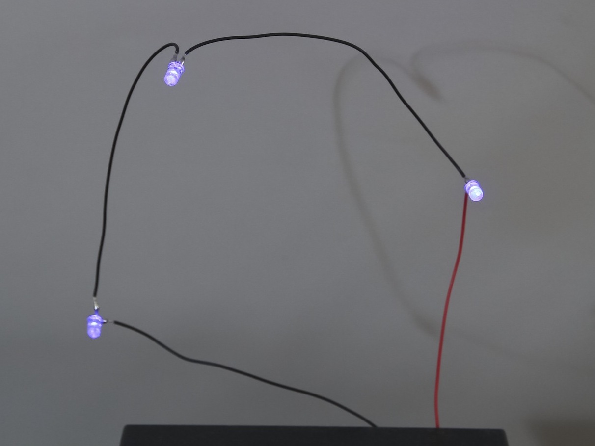
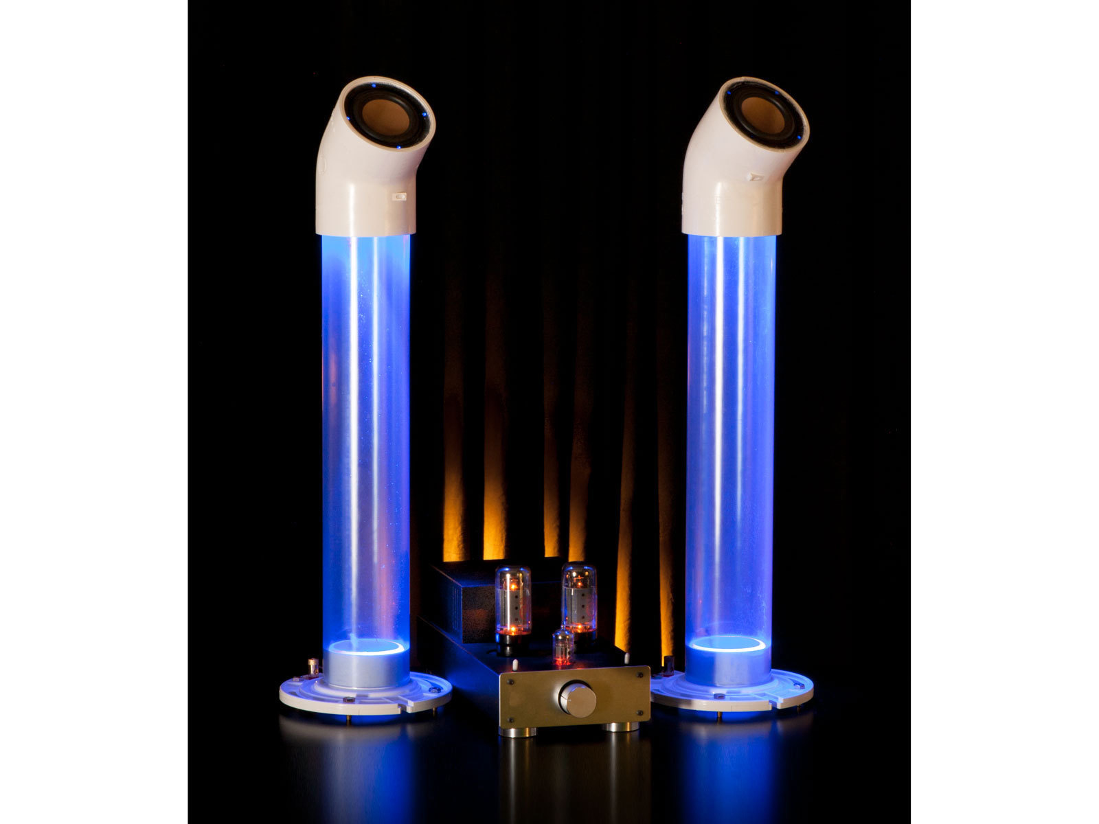
I connected an iPod (playing ZZ Top’s “La Grange”) to a 20-watt amplifier and a small speaker, and played around with different configurations of LEDs on the speaker wire. The best visuals, I found, came from simply connecting 3 ultra-bright LEDs in series, in parallel with each speaker. Voilà! At moderate volume and above, the same audio signal both drove the speaker and pulsed the LEDs in time with the music — and I discerned no difference in the speakers’ sound with or without the LED load.

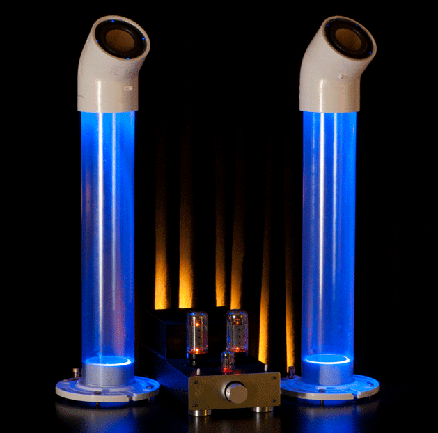
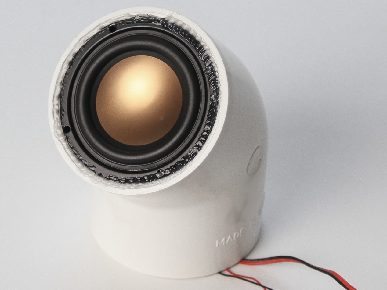
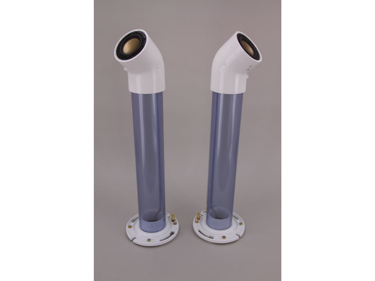
Introducing the Sound-O-Light Speakers. They’re easy to build, they get surprisingly good sound out of their single 3″ drivers, and they look hella cool.

Materials

  • Speaker drivers, 3″ diameter, round (2) I used HiVi B3N drivers, which are popular, cost about $10 each, and use standard car-audio spade connectors. If you have a different 3″ driver in mind, by all means give it a try.
  • PVC pipe, clear, 3″×20″ lengths (2) Some sources sell this by the foot while others only sell 10′ lengths. Since this pipe costs roughly $15/foot, it makes sense to find a supplier that can sell the exact 40″ quantity required. Check local industrial plastics suppliers first, but there are also several online sources.
  • PVC pipe flange fittings, 3″, white (2) ABS fittings may also work, but ABS is not as stiff or dense as PVC, which may affect audio quality.
  • PVC pipe elbow fitting, 45°, 3″, white
  • Audio binding posts (4) typically sold in pairs
  • Aluminum tubing, 1/2″ outside diameter (OD) × 17-1/2″ long (2)
  • LEDs, 5mm, ultra-bright (6) your choice of color(s); they can be different for each speaker.
  • Spade connectors, female, .110″ (4) standard car audio connector
  • Cable clips, adhesive-backed, plastic, sized to hold coaxial cable (6) for holding LEDs. You can also use hot glue.
  • Speaker cable, 2-conductor, 6′ or other paired wire. We used a red/black pair to help identify the polarity for the LED circuit.
  • Hookup wire, insulated, 18–22 gauge, 4′
  • Silicone adhesive in squeeze tube

For bass reflex speakers:

  • Bolts, #12 round head, 3/4″ long, with matching nuts (8)
  • PlastiDip or 6″ hardwood square (optional) to prevent bolts from scratching floors or furniture

For acoustic suspension speakers:

  • PVC or other plastic sheet, 1/4″ thick, 1′ square minimum Look in the window and door aisle at your home improvement store.
  • PVC cement
  • Silicone caulk

For powered/transistorized option:

  • Snaps for 9V battery (2)
  • 9V batteries (2)
  • Transistors, NPN, TIP31 type (2)
  • Resistors, 220 (2)
  • Switch, on-off toggle
  • Perf board

Make Amends

In Volume 31’s “Sound-O-Light Speakers,” the vented build option is not a true bass reflex design (see reader Louis Lung’s letter, here). Also, author Bill Gurstelle’s Night Lighter 36 spud gun project is from MAKE Volume 03, not 04.

What will the next generation of Make: look like? We’re inviting you to shape the future by investing in Make:. By becoming an investor, you help decide what’s next. The future of Make: is in your hands. Learn More.

Project Steps

Cut and glue the tubes.

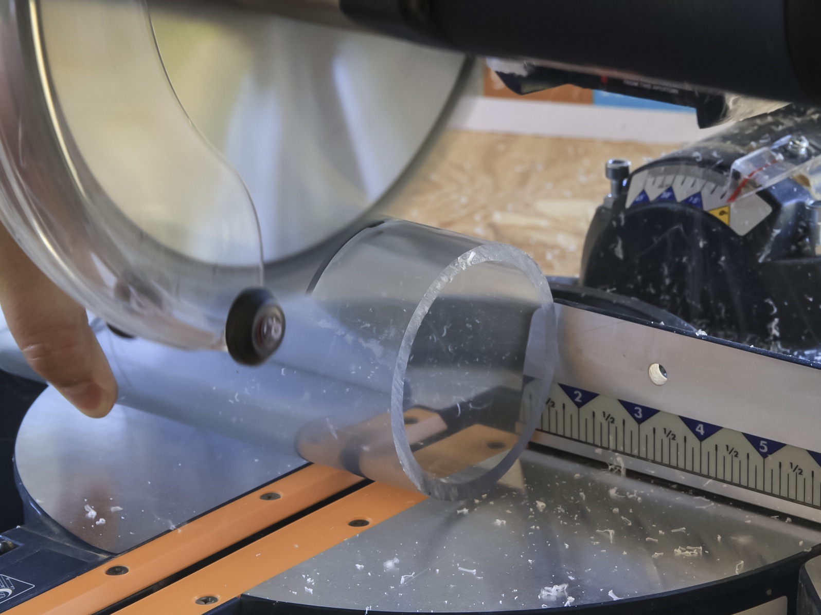
Cut the clear PVC and aluminum tubing to length. Drill two ¼” holes in each PVC tube, 1″ from each end and in line with one another, parallel to the tube.

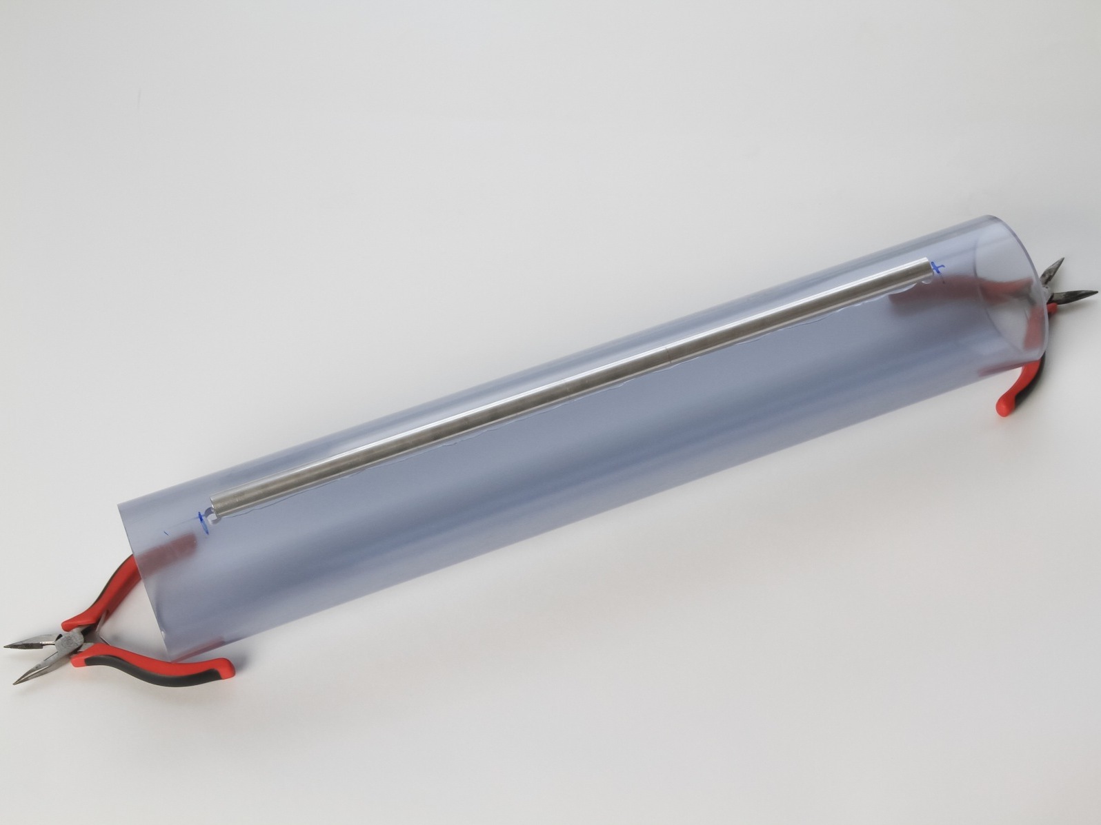
Use a thin bead of silicone adhesive to attach the aluminum tube to the PVC pipe between the 2 holes. Let dry completely.

NOTE: These instructions describe the construction of a single speaker. Perform each step twice to make a pair.

Connect the wiring.

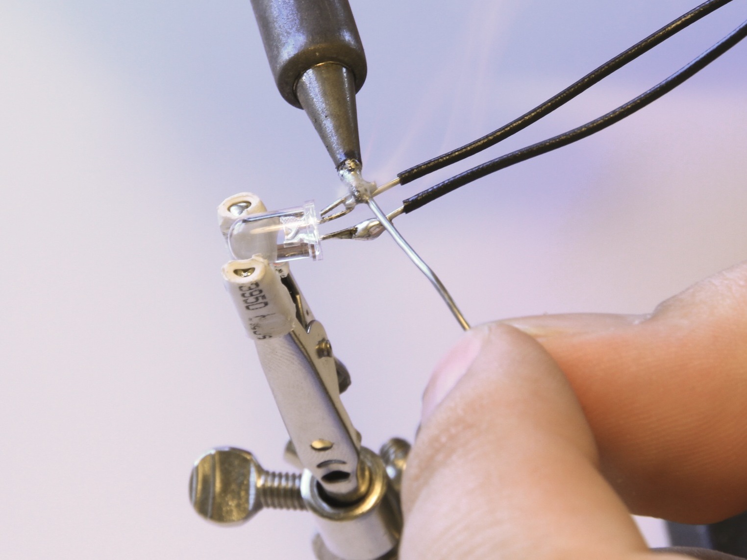
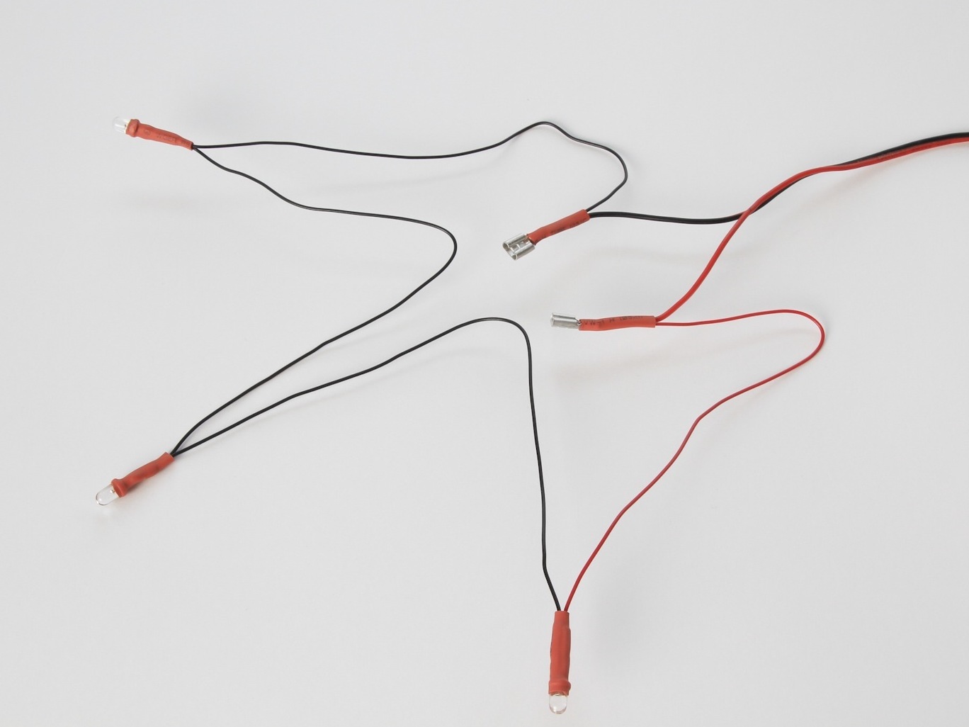
Cut and strip the ends of four 6″ lengths of hookup wire (8 lengths total for both speakers). Solder 3 LEDs together in series, with wire leads in between and at each end. Orient all LEDs the same way, with neighboring LEDs connected anode-to-cathode (longer leg connected to shorter leg).

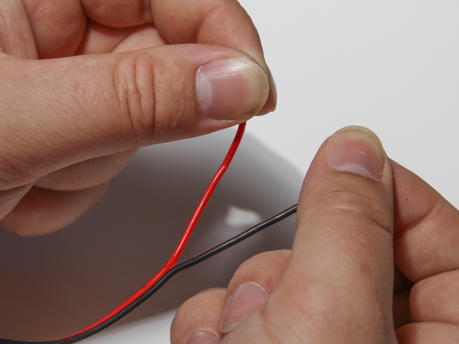
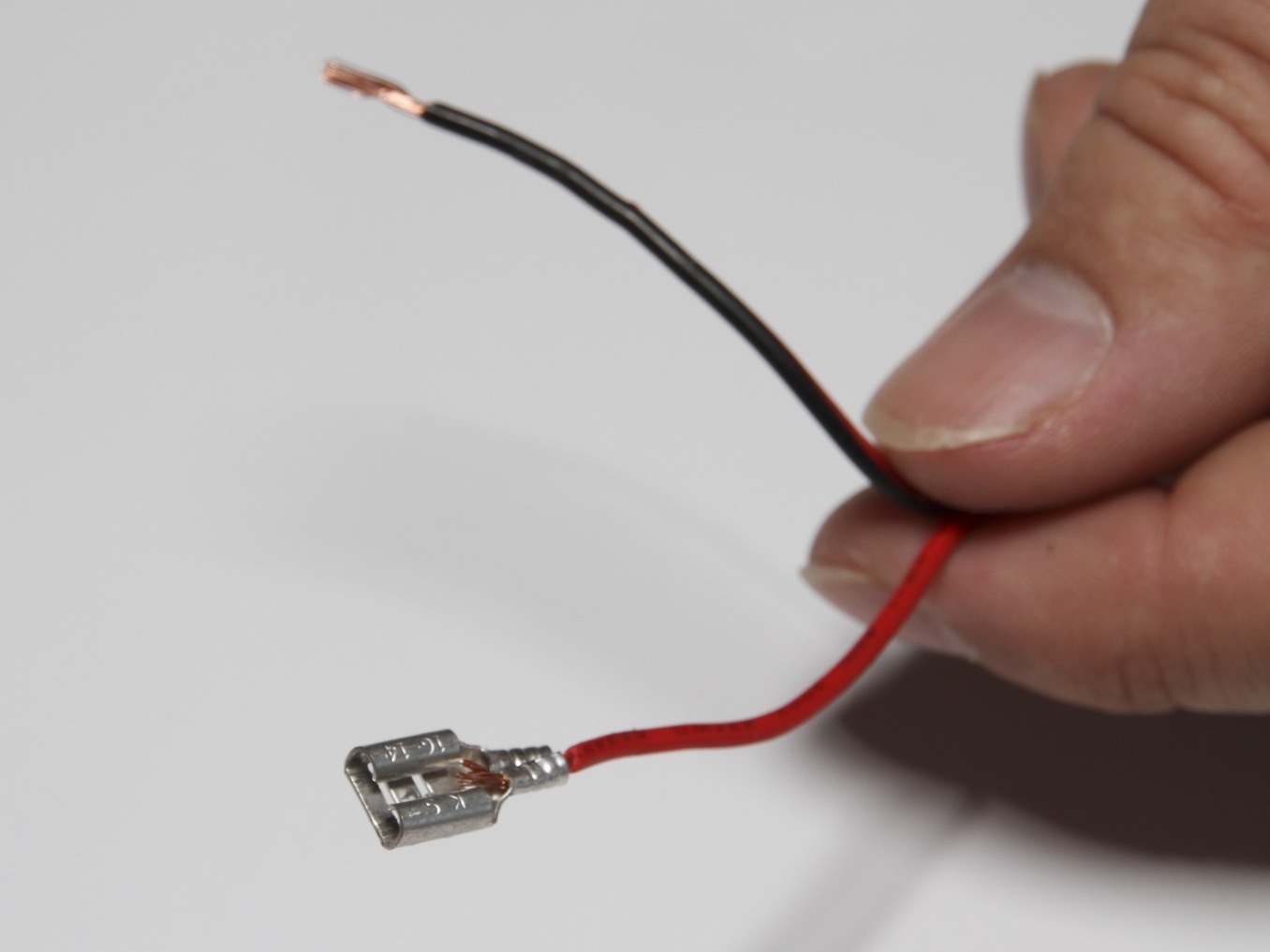
Cut a 32″ length of speaker cable or other paired wire, peel the wires apart at each end, and strip the ends. Crimp and solder a female spade connector to each wire at one end of the cable.

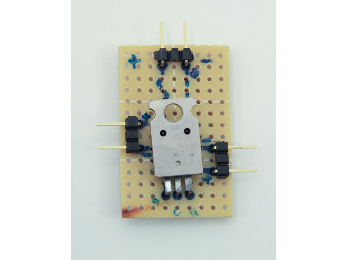
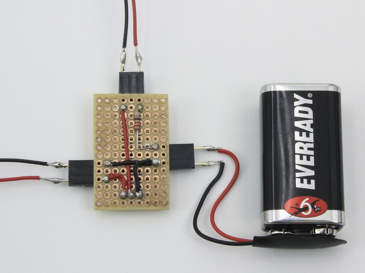
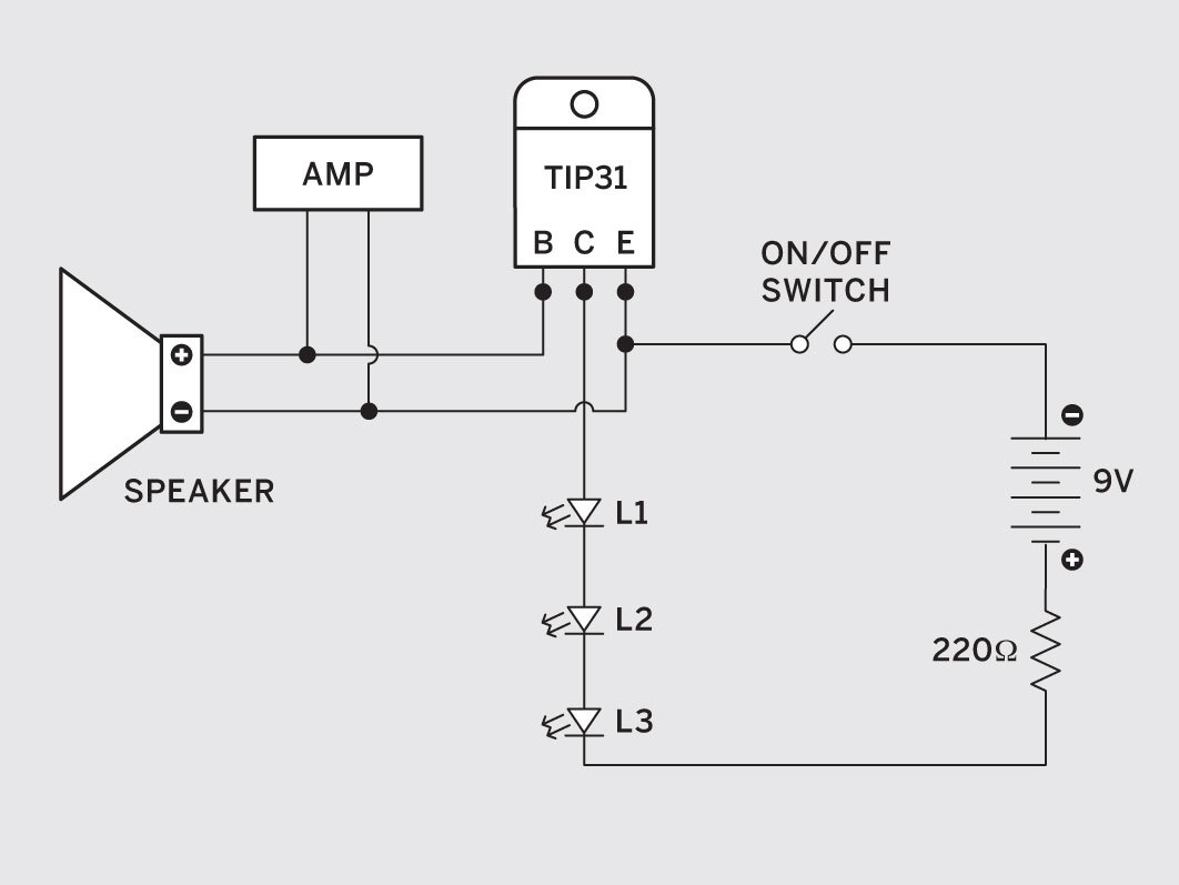
(Optional) If you want to power the LEDs with 9V batteries so they flash at lower volumes, wire the circuit shown here.

Solder the battery snap’s red wire (+) to the LED chain’s anode, and the snap’s black wire (–) to the TIP31 transistor’s emitter, the right leg as you face the front side with the legs pointing down. Then connect the LED cathode to the transistor’s collector, in the center.

Wrap each stripped wire end of an LED chain around the copper base of each spade connector, and solder in place. (With the battery circuit, connect the LED’s cathode end and the transistor’s collector, the middle leg.) The LED anodes and cathodes can be oriented in either direction on the speaker wire.

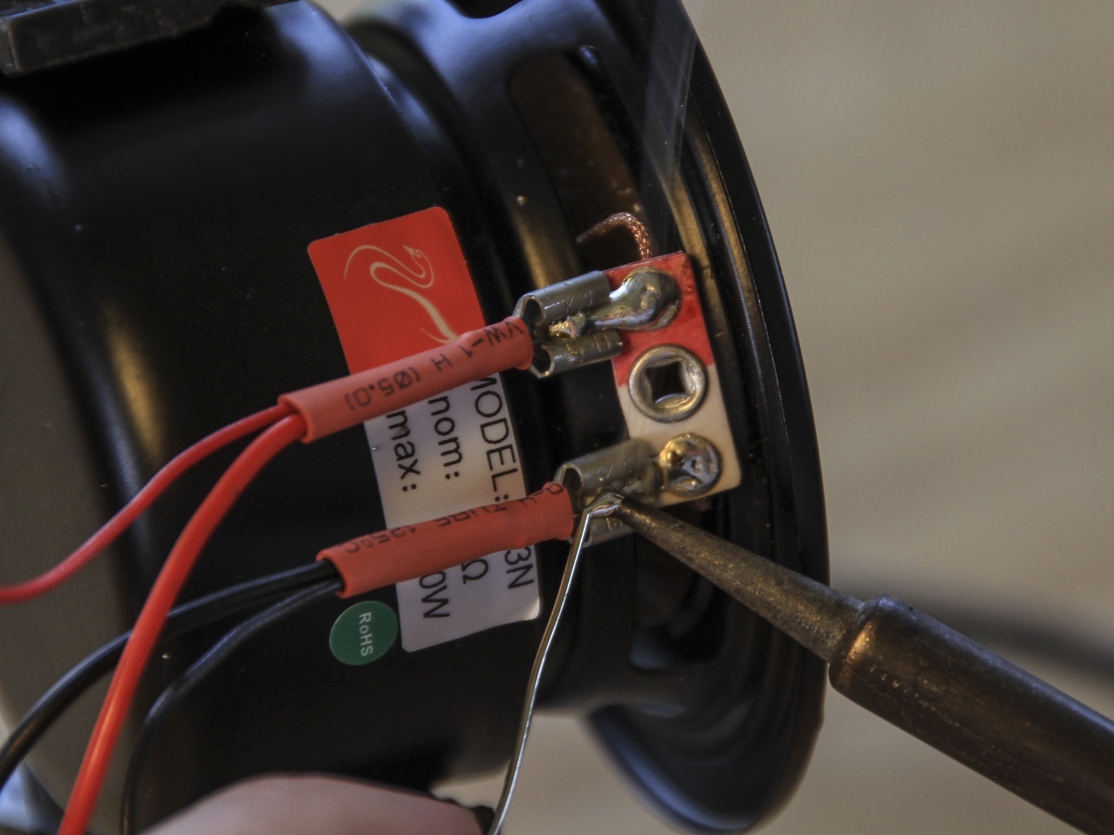
Plug the female spade connectors onto the speaker terminals and solder in place.

Test the wiring by connecting the speaker/LED assembly to an amplifier and playing music. During loud passages (or more often, if powered), the LEDs should pulse in time to the music. If the LEDs do not light, check the quality of the soldered connections and make sure all LEDs are connected positive to negative.

Perform final assembly.

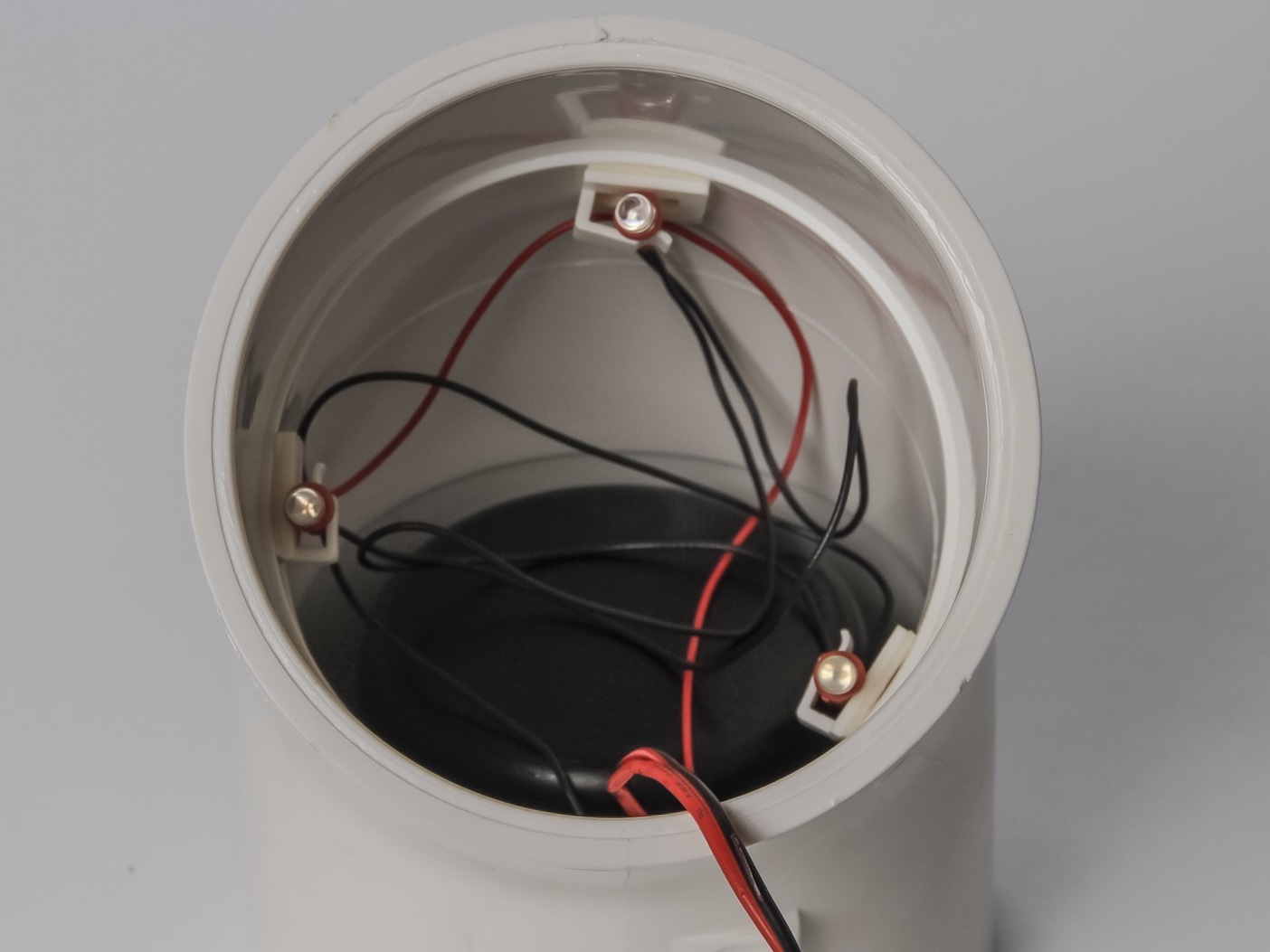
Attach the cable clips to the interior of the PVC elbow fitting so they will hold and point the LEDs down the PVC pipe, spaced 120° apart. They should sit well up inside the fitting to avoid being loosened when you insert the pipe. You can also secure them with hot glue.

Place the speaker into the elbow, center it, and then secure it in place with silicone sealant around the perimeter. Let the sealant dry completely.

Turn the elbow upside down and clip or glue the LEDs inside, making sure they will point down the tube when the speaker is on top.

Prepare the PVC flange to be the base of the speaker.

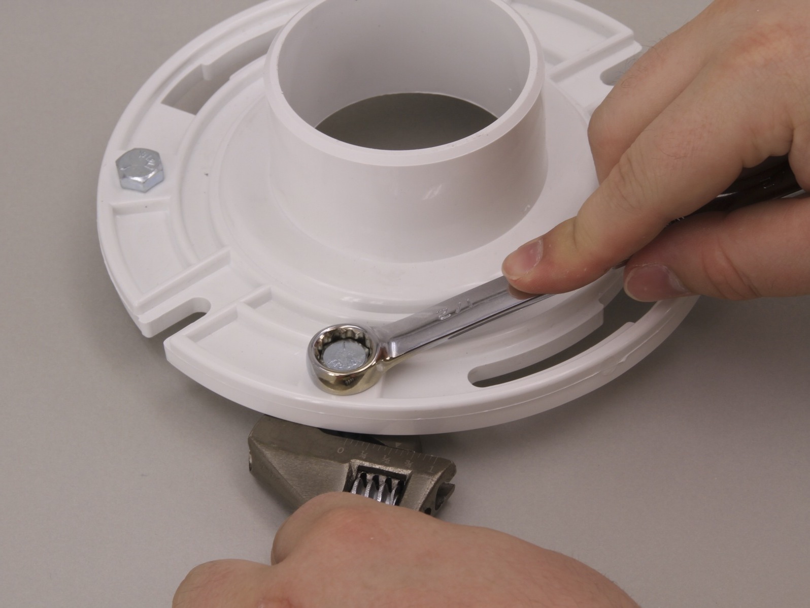
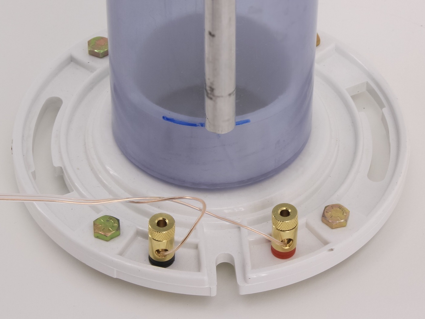
For a bass reflex cabinet (shown here), run 4 bolts down through the mounting slots around the flange, securing them with nuts on either side. If your flange lacks slots, drill ¼” holes.

For an acoustic suspension cabinet, use a saber saw or similar tool to cut two 5″ rounds out of ¼”-thick PVC. Glue them into the underside of each flange, then seal gaps with silicone caulk.

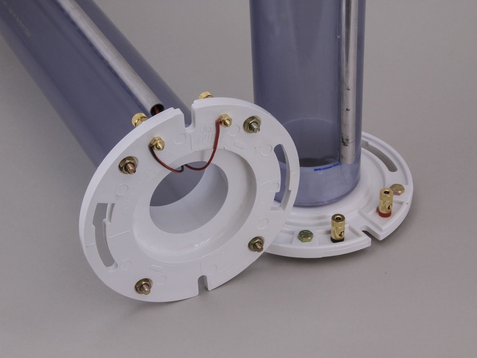
Drill two ¼” holes in the flange and install audio binding posts with supplied nuts.

Thread the speaker wire dangling from the PVC elbow out through the top ¼” hole in the clear PVC pipe, down through the aluminum tube, and back in through the bottom hole in the PVC pipe.

Press the elbow firmly onto the top of the clear pipe, and press the flange onto the bottom. Temporarily rest the speaker on its side, wrap a speaker cable wire around each binding post terminal, solder in place. You’re done!

Rock your Sound-O-Lights.

At low volumes, the Sound-O-Light LEDs won’t glow, but at moderate volumes and above, they will pulse with the sound — the louder, the brighter.

As with any speaker pair based on small drivers, you can fill out the sound by adding a subwoofer, and please let me know if you build one that glows.

Experiment with more plastic pipe speakers.

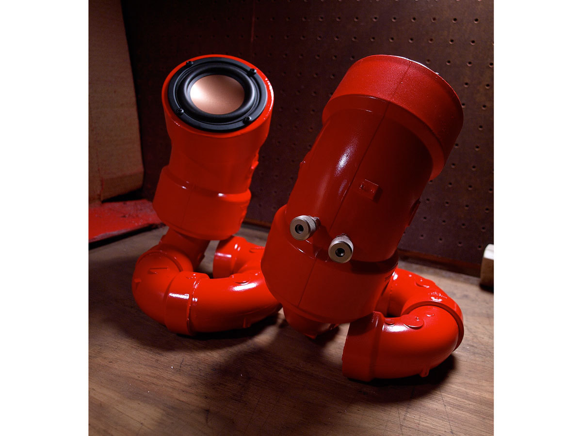
Eric Nelson, Rob Sampson, and others make amazing-looking speakers from plastic pipe, following more advanced designs than the Sound-O-Light.

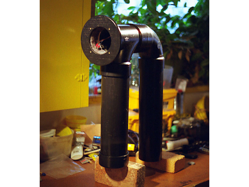
Nelson uses PVC to make desktop-sized acoustic creations (Red Lobsters, 1st photo).

Sampson makes larger speakers using standard black ABS plastic (Drooping Didgeridoo, 2nd photo).

Sampson’s include “quarter wave” chambers that resonate well because their unfolded length exceeds ¼ of the wavelength in air of the lowest frequency they carry, which is about 9½’ for a 30Hz rumbling bass tone.

Conclusion

This project first appeared in MAKE Volume 31, page 80.