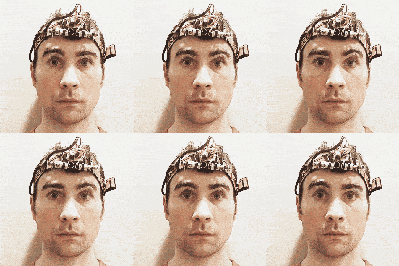
RC Eyebrows

Here’s how to build a set of remote control eyebrows from an old headlamp and a small handful of parts. Two small motors mounted to the headlamp will be attached by thread to your eyebrows for a natural look.

Beyond its obvious practicality, this project makes a great introduction to DC motor control, infrared remote control, and moving from working with an Arduino to working with the bare ATMega328 chip. These concepts are combined with some minimal extra circuitry.

The end result will be a great conversation piece, that is… if you don’t stab your eye with a toothpick. My implementation supports calibration, independent control of each eyebrow, and a 1- to 9-way waggle feature. Expressions vary from skeptical to shocked to very, very shocked.

Because you’ll probably be working with a different remote control than mine, you’ll need to experiment with decoding the buttons and assigning them to functions. Reverse-engineering household junk is a satisfying way to save money and reduce e-waste. You’ll need to be familiar with Arduino-style C code to adapt the supplied source code to suit your own remote control.

YouTube player

What will the next generation of Make: look like? We’re inviting you to shape the future by investing in Make:. By becoming an investor, you help decide what’s next. The future of Make: is in your hands. Learn More.

Project Steps

Step 1: Breadboard the circuit around the Arduino

We’ll start by using the Arduino to do some prototyping and testing. We’ll use the ATMega328 controller later, once we’re satisfied that all the pieces are working well together.

On a breadboard, wire up the VS838 IR receiver, L293D, motors, etc. to your Arduino using the following diagram:

brows-arduino

Step 2: Install the IRLib library into your Arduino environment

We’ll be using the IRLib library to interact with the VS838 (or equivalent) IR receiver. Install the library into your Arduino environment by following the instructions there.

Note that IRLib should be able to recognize the most common remote control protocols, but at least in the case of my Pioneer remote control, it didn’t know how to decode the data. Fortunately the library supports using a “fingerprint” hash from raw data, so button presses can still be reliably detected. This technique should work with recognized protocols as well, so it shouldn’t be necessary to change the code overmuch even if your remote’s protocol is recognized by IRLib.

Step 3: Upload the “brows.ino” sketch to the Arduino

You’ll find the required Arduino sketch available from this repository. Once the sketch is uploaded to the Arduino, open the serial console and try pressing remote control buttons with the remote facing the IR receiver. You should see hash codes corresponding to unrecognized button presses. (The “brows.ino” sketch sends these to the serial port when it doesn’t recognize them.)

Step 4: Hook up the button hashes to the brow functions

In the source code for the sketch, you’ll see “case” statements with hash codes for remote control buttons like:

case 0xDF604FDC: // Left brow, large up

Your remote control will probably have a different number and layout of buttons, so you’ll have to experiment with this to find a good mapping.

As you change these hashes, upload the sketch and test whether your motors are working according to the button you press.

Step 5: Add the ATMega328 to the breadboard

So far we’ve been using the Arduino to run the motors. Let’s add the ATMega328 chip to the breadboard and program it instead. Move the data connections that are currently attached to the Arduino so that they connect to the ATMega328 chip instead, per this diagram:

brows

Add the power and ground connections to both sides of the ATMega328 following the diagram.

Do not hook up the battery yet. For now we’ll continue to use the Arduino for power.

Step 6: Hook up the Arduino to the ATMega328 as a programmer

We won’t be using the Arduino to run our sketch directly anymore; we’ll be using it to program the ATMega328 on the breadboard instead. Connect your Arduino to the ATMega328 following this diagram.

Because our circuit does not require any of the pins used to program the ATMega328, you can leave the Arduino connected until you’re ready to move the circuit to perfboard.

Follow the instructions at https://www.arduino.cc/en/Tutorial/ArduinoISP to flash the bootloader, making sure to choose “ATMega328 on a breadboard (8MHz internal clock)” as your board. If you’re able to flash the bootloader, that’ll confirm that you’ve hooked the ATMega328 up to the Arduino properly.

Arduino Setup

Step 7: Upload the “brows.ino” sketch to the ATMega328

Now that your Arduino is set up to program the ATMega328 chip, upload your sketch. Your breadboarded circuit should start working with the remote control, now being driven by the ATMega328. The Arduino is now just providing power.

This is your last chance to (easily) tweak the program; make sure you’re happy with it before proceeding. Then remove the Arduino entirely; try hooking up the battery pack and verify that it still works.

Step 8: Move the circuit to perfboard

You now need to move everything on the breadboard to the more permanent perfboard, soldering connections as you go. Complete the circuit using the empty DIP sockets in place of the ICs, and only add the ICs when you’re finished. This will help prevent damage to the ICs during soldering from static discharge or overheating; using a socket for the ATMega328 will also mean program changes aren’t impossible, just annoying. When laying out the components, consider the physical space available on the headlamp. When transferring circuits, I find it easiest to remove each wire from the breadboard as I go; when the breadboard is empty, that means I’m finished.

Once you’re finished, apply power from the battery pack and check that it’s working.

Step 9: Assemble the hardware on the headlamp

The details will depend on your headlamp. The motor placement is probably the most important; on my old Petzl, once the bulb assembly was removed, a single zip tie per motor was sufficient to affix it securely. You’ll want each motor’s spindle centered over an eyebrow.

To attach each motor’s spindle to its bobbin, I simply wrapped a strip of sturdy adhesive tape around the spindle until the bobbin was a tight friction fit. This has the added benefit of slipping under tension.

Congratulations, you’re ready to never ever affix it to your face!

Eyebrow HeadlampRC Eyebrow HeadbandRC Eyebrow Headband

Step 10: Don’t affix it to your face

You should never attach this to your face for health and safety reasons. Specifically, you shouldn’t wind thread around each bobbin and tape the dangling end to your face with a piece of band-aid adhesive just below the eyebrow (above the eyelid). You also shouldn’t tie a small piece of toothpick to the end of the thread to give the band-aid something to stick to.

Going Further

For more permanent attachment, don’t ever consider eyebrow piercings clipped with tiny carabiners.

There are many left-over I/O pins on the ATMega328, so making your eyebrows sensor-driven is easy. For example, an acoustic sensor could raise eyebrows in case of sudden noise. Or connect a wi-fi module and help pioneer the Internet of Things On My Face.

The thread from the motors can be attached to hooks under your lips for a convincing smile when your muscles just aren’t feeling it. For both eyebrow and smile control, an additional H-bridge would support more motors.

Now that you’re basically a cyborg, a world of new possibilities is yours.

YouTube player