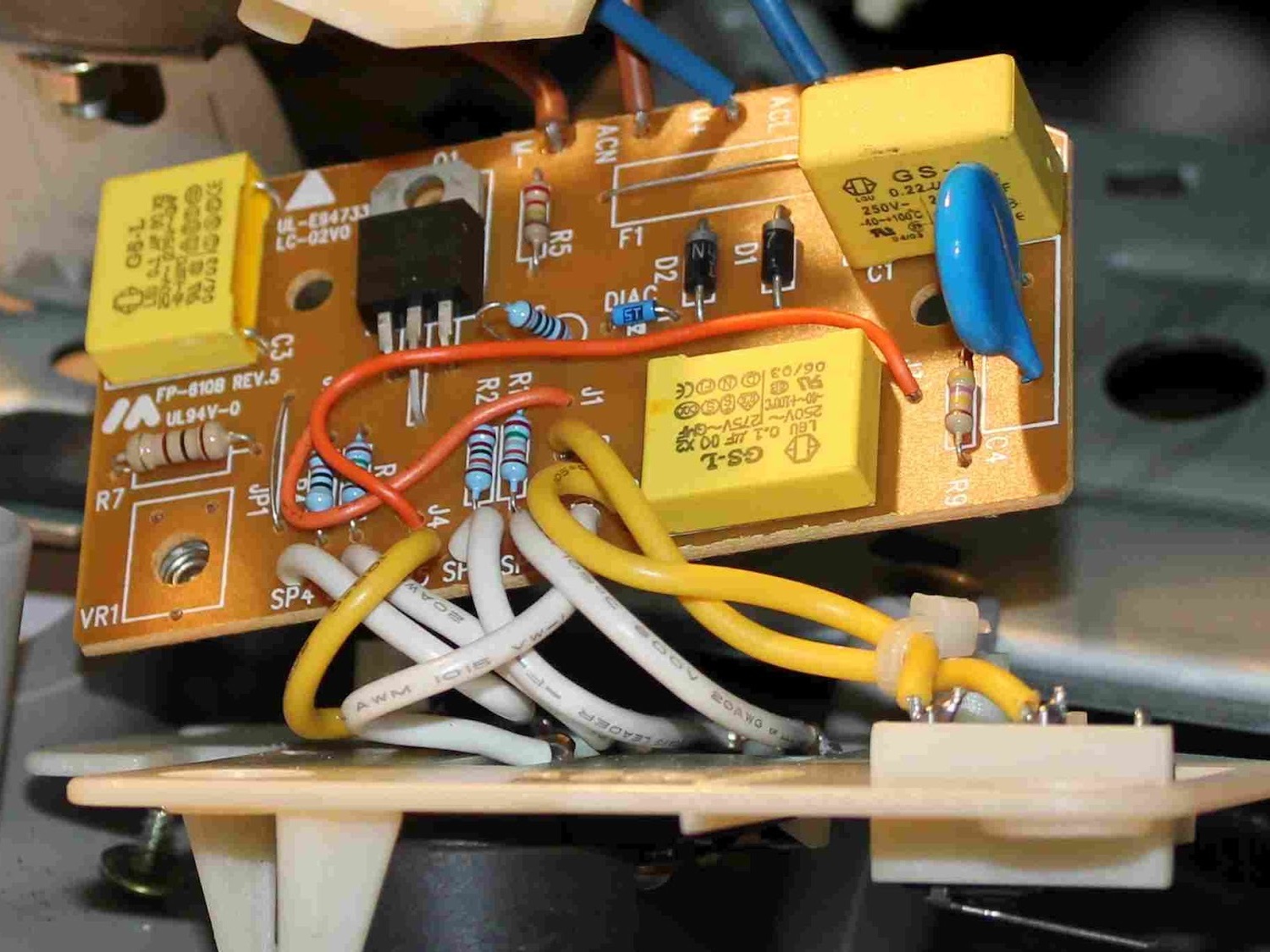
A common fault in motorized kitchen appliances is failure of the speed control Triac and/or associated Diac. This teardown shows you how to get to and replace the Triac and Diac in a Sunbeam food processor.

What will the next generation of Make: look like? We’re inviting you to shape the future by investing in Make:. By becoming an investor, you help decide what’s next. The future of Make: is in your hands. Learn More.

Project Steps

The Sunbeam food processor. When plugged into the wall it starts at full speed, and the speed control dial can’t turn it off or adjust the speed.

This is a common mode of failure when a speed control Triac has gone short circuit, or failed partially, becoming easily triggered. This usually happens after a voltage spike from an inductive load, like the motor in the appliance, or something else plugged in nearby.

Do not under any circumstances dismantle the unit with power applied, as it is double insulated and you could be electrocuted and a residual current earth leakage device will probably not be able to trip to save you.

If you are not confident with mains wiring, get someone who is to do this repair for you.
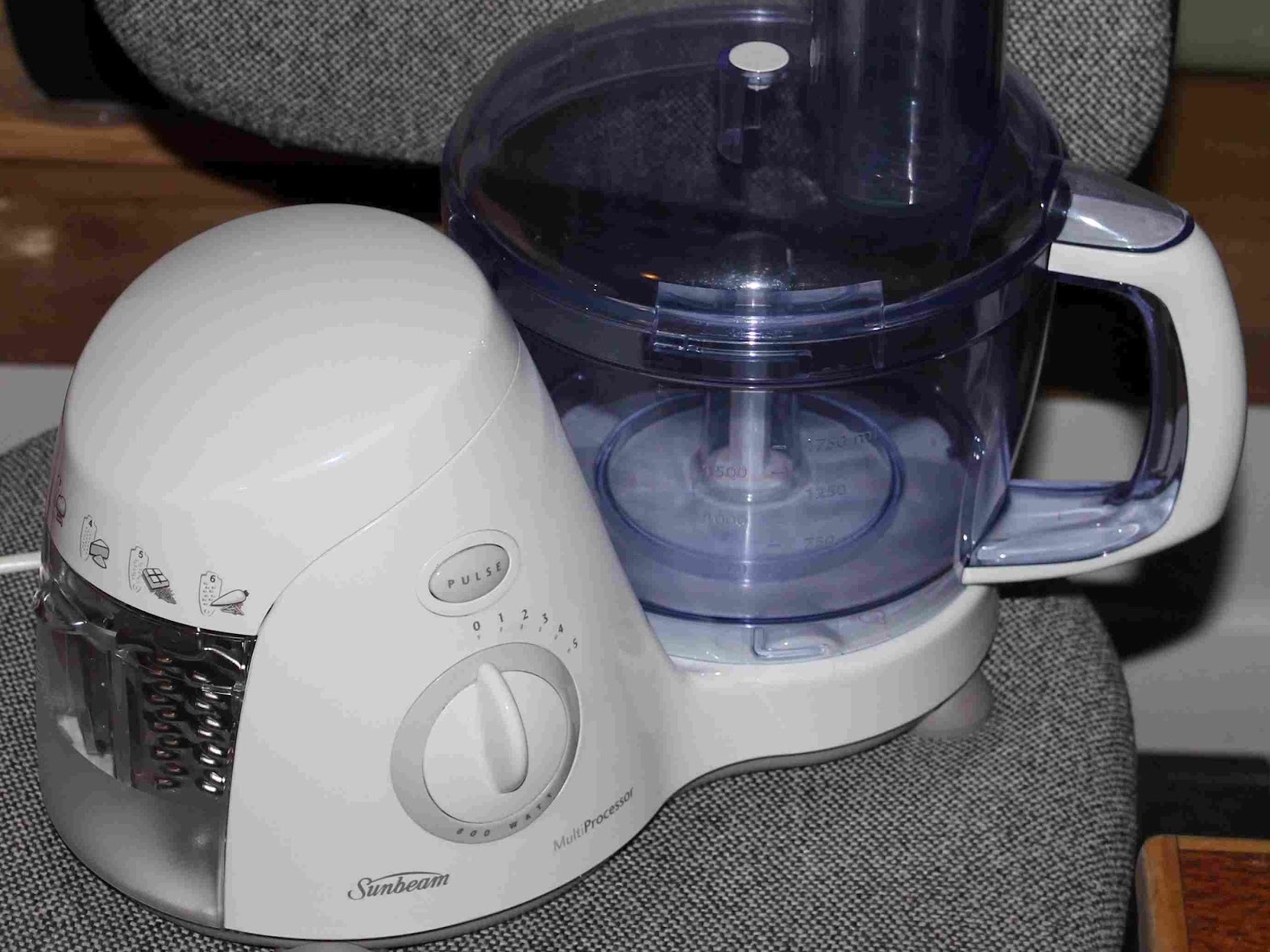
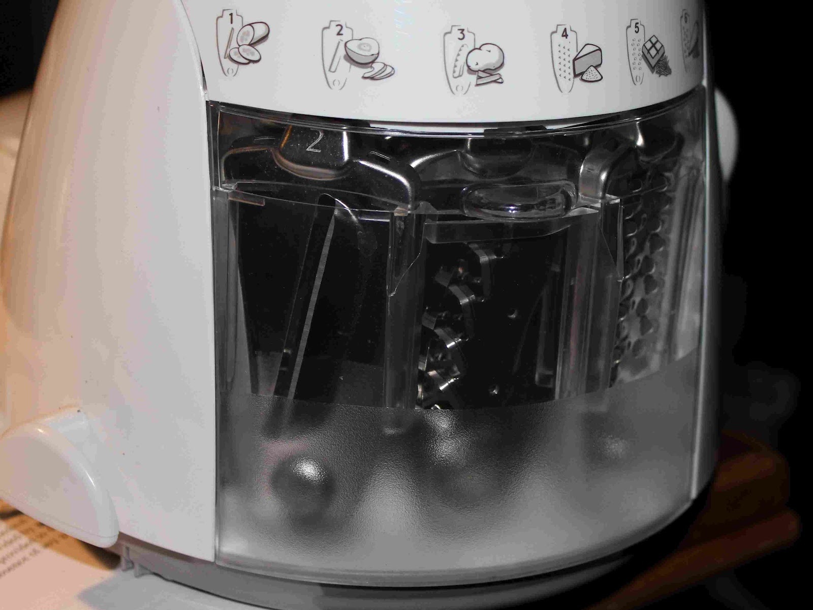
The utensil drawer is removed by tilting it out and pulling it out.

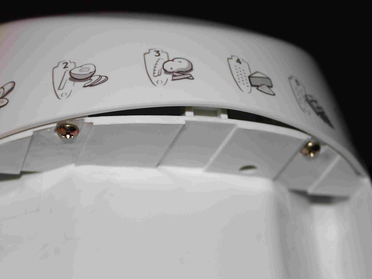
This exposes two screws which need to be undone.

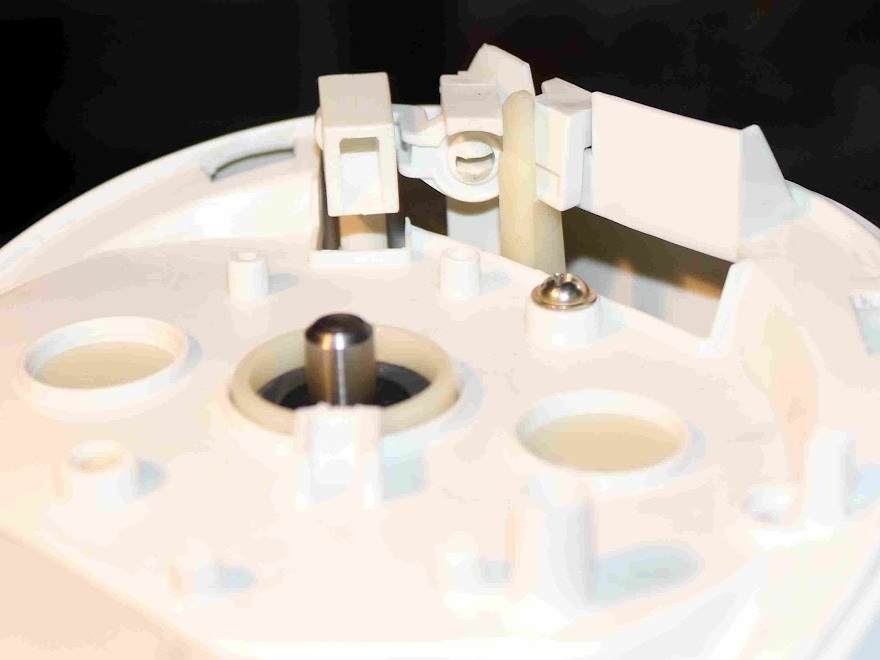
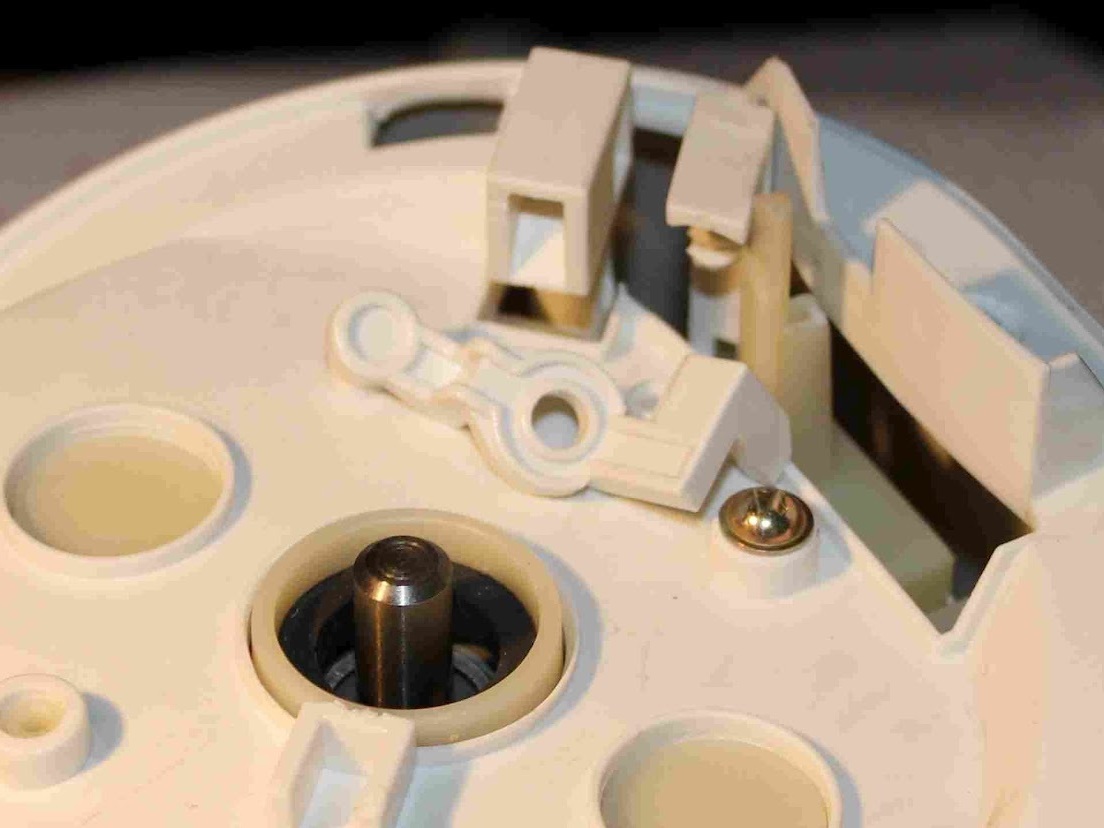
With the 2 screws removed from the utensil alcove, the lid of the unit can be carefully popped off revealing the safety interlock mechanism and another screw.

Carefully pry the toggle off of the plastic split pin, and remove it from the associated linkages.

Remove the screw.

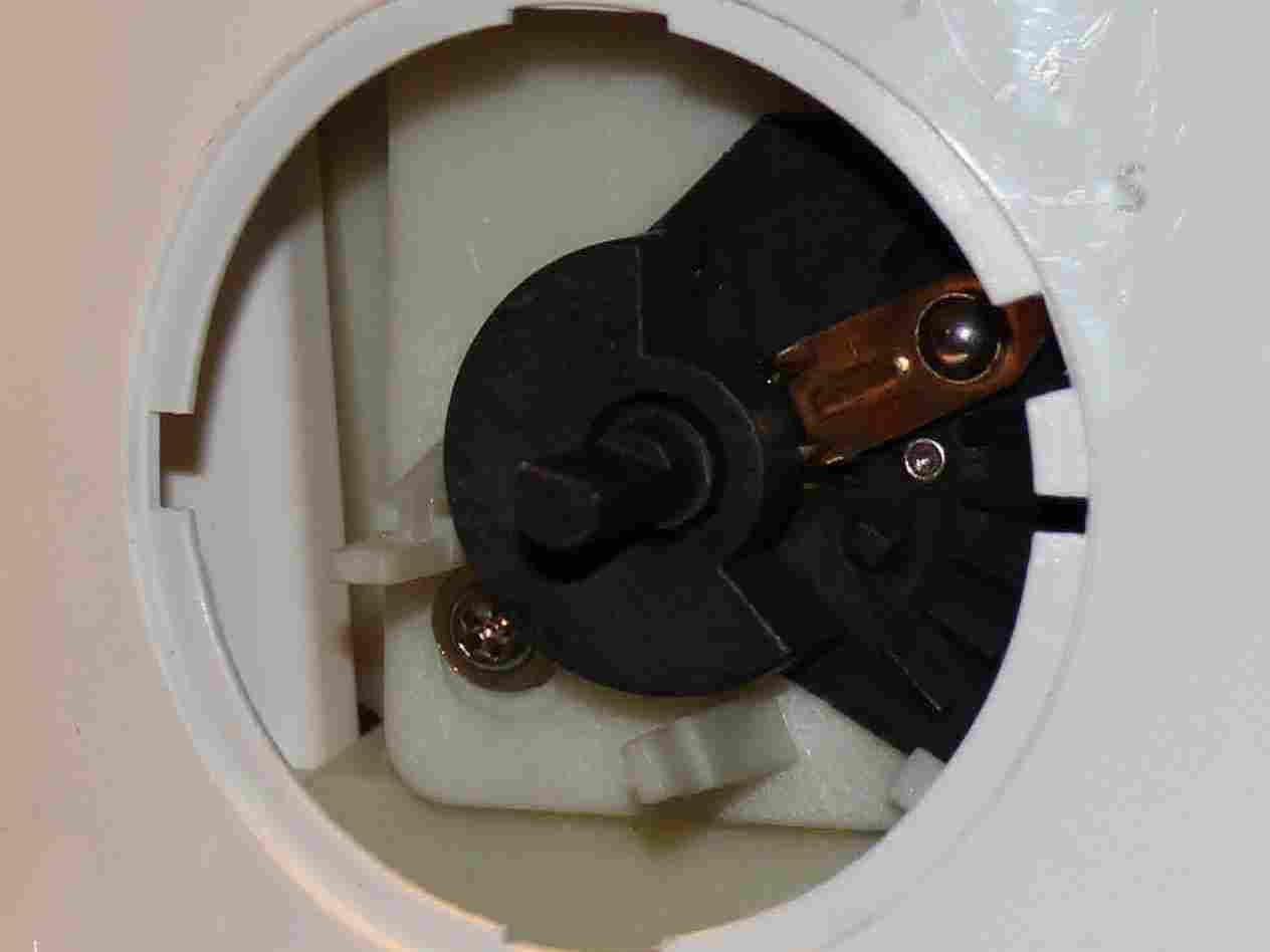
Next, the speed control dial must be carefully popped out.

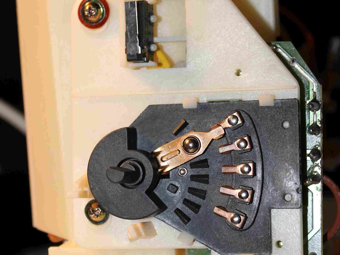
This exposes the rotary switch underneath.

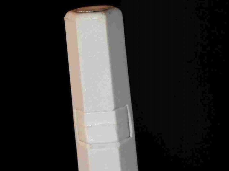
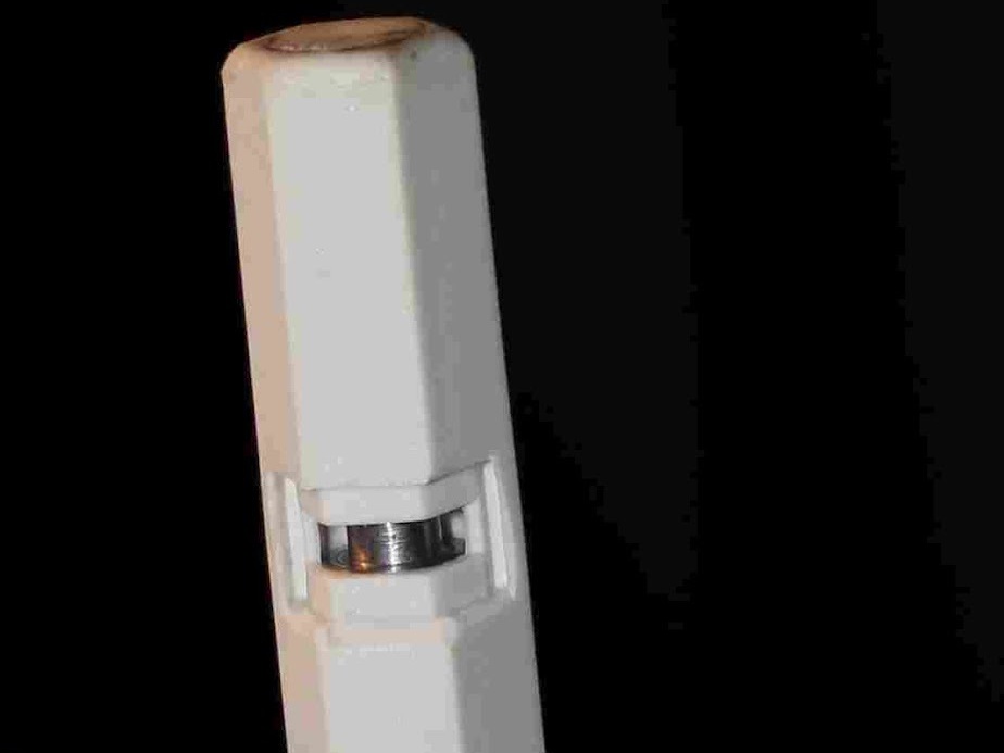
Next, the transmission spindle must be freed. Identify the plastic locking insert on the spindle and carefully pop it out.

This allows the plastic spindle to be lifted off of the metal drive shaft, which will allow the entire housing to be removed.

Undo all of the screws on the underside of the food processor, including the recessed one in the middle. You should now be able to lift the entire upper housing off of the base and internals.

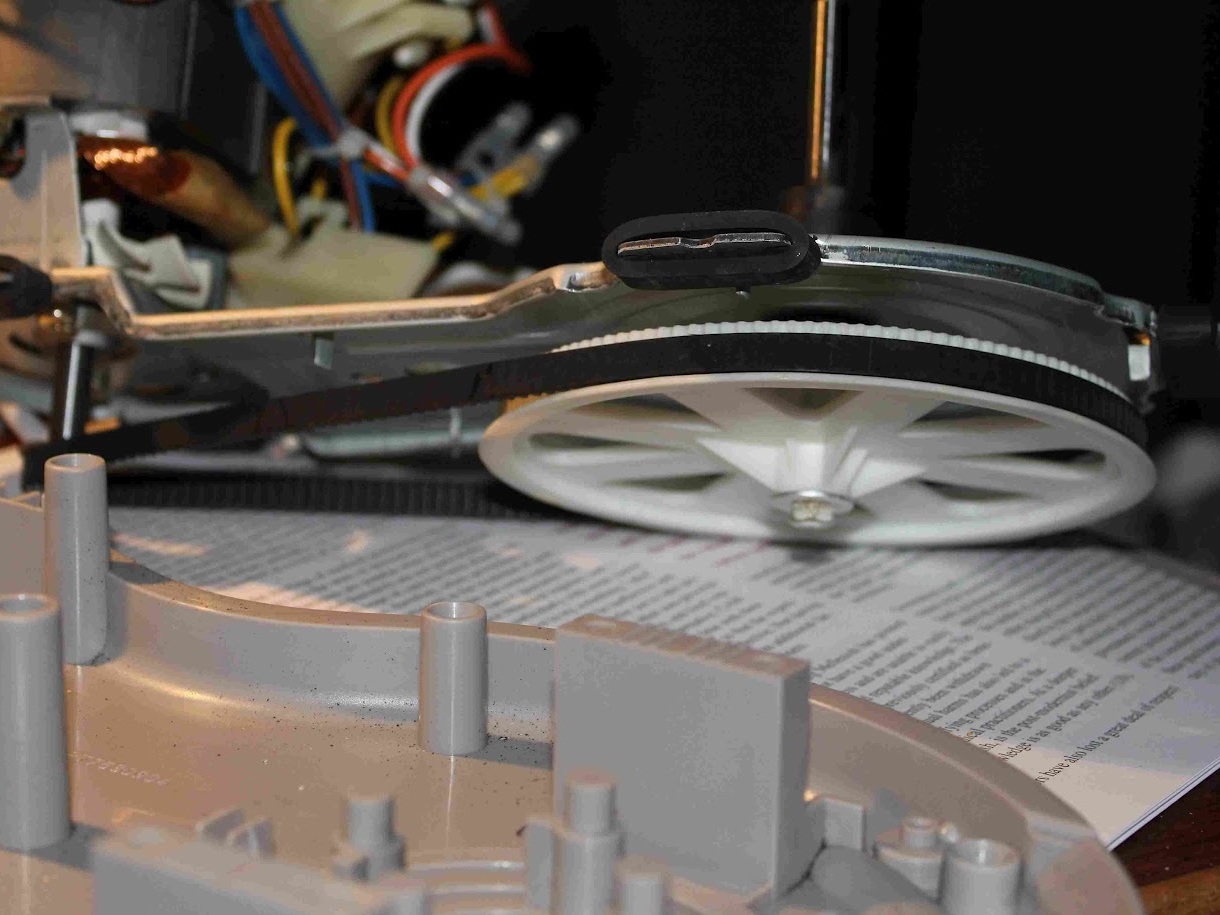
The drive mechanism can be inspected by lifting it up off the base plate.

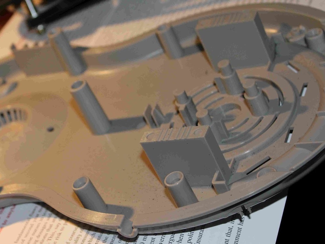
The base plate is shown.

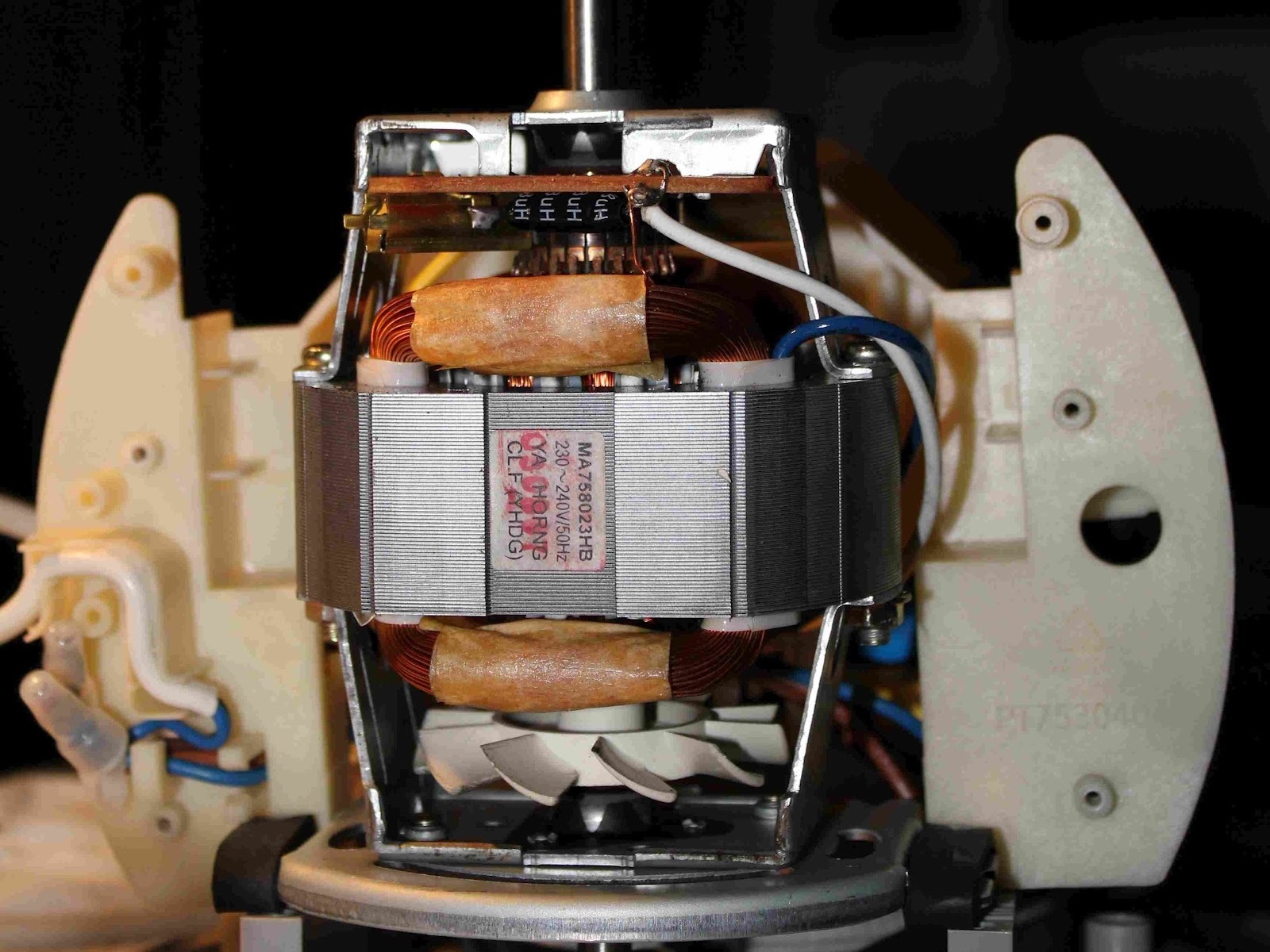
The motor housing can be inspected, and the first photo shows the armature and carbon brushes of the motor.

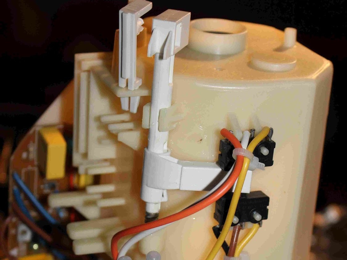
The second photo shows the safety interlock switches, which are actuated via the toggle you removed earlier, when the mixing bowl is locked into place.

The remaining third side of the motor housing has the switchboard/PCB subassembly attached, with the “pulse” microswitch and rotatory on/off and speed control switch exposed

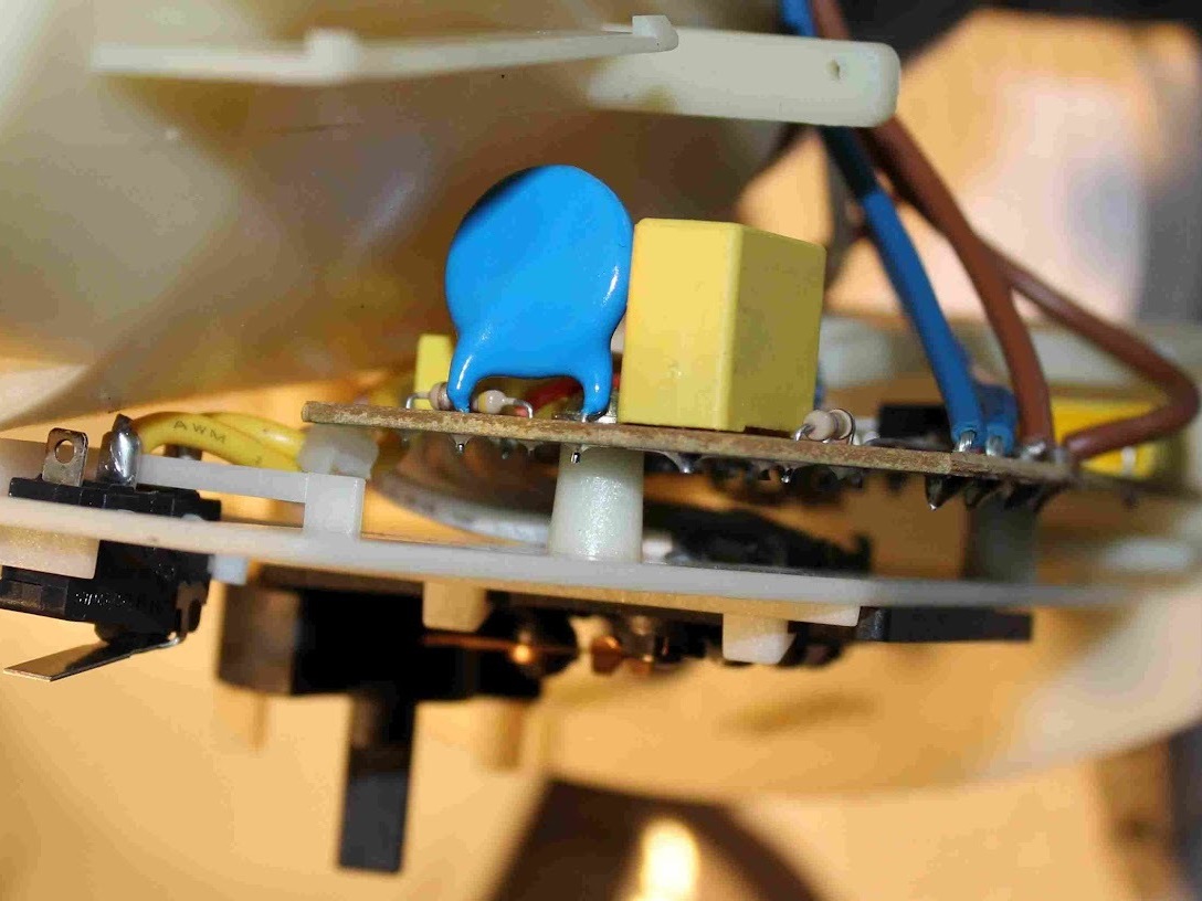
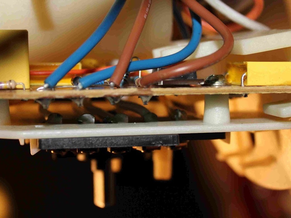
These photographs show the switchboard and speed control PCB still attached to the motor housing in more detail, and the wires passing between them.

The second photograph shows the active and neutral coming into the speed control PCB, and the active and neutral going off to the motor.

If your motor is on all the time, the problem is likely to be the PCB sitting between the power coming into the PCB, and the power going out from the PCB to the motor, i.e. the PCB is the problem.

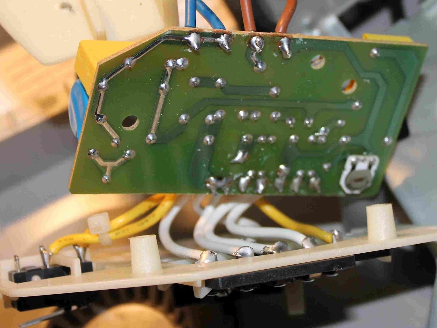
The switchboard/PCB subassembly can be removed from the motor housing by undoing two screws. The switchboard can be removed from the PCB with removal of another two screws.

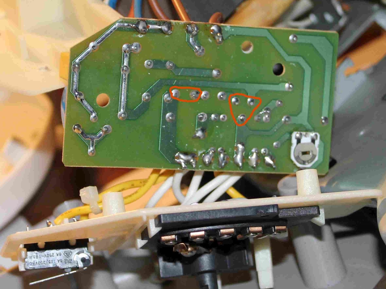
The second photo shows the PCB pads that interest us outlined in red. They are the PCB pads for the TO-220 BT137 600V Triac, and the two pads for the DB3 Diac.

The third photo shows the TO-220 Triac (black with three legs), and the DB3 diac to its right (small blue cylinder with the PCB “Diac” label above it).

Replace the DB3 Diac and the BT137 Triac with new ones (costing a few dollars at most) after desoldering the old ones from the PCB.

Reassemble the unit completely, following the steps in reverse, and apply power only once it is safe to do so.