One of the most common problems in building small robots and other electromechanical projects is that off-the-shelf DC motors just run too fast for many applications. Sometimes a mechanical fix like a gear or capstan drive is the solution, but many times you’ll want to skip the additional noise, space, and precise construction that mechanical drive-trains entail. In these cases, a “direct-drive” arrangement, in which the motor shaft is directly coupled to the load it turns, is likely best. And you’ll find yourself in need of an electronic speed controller.
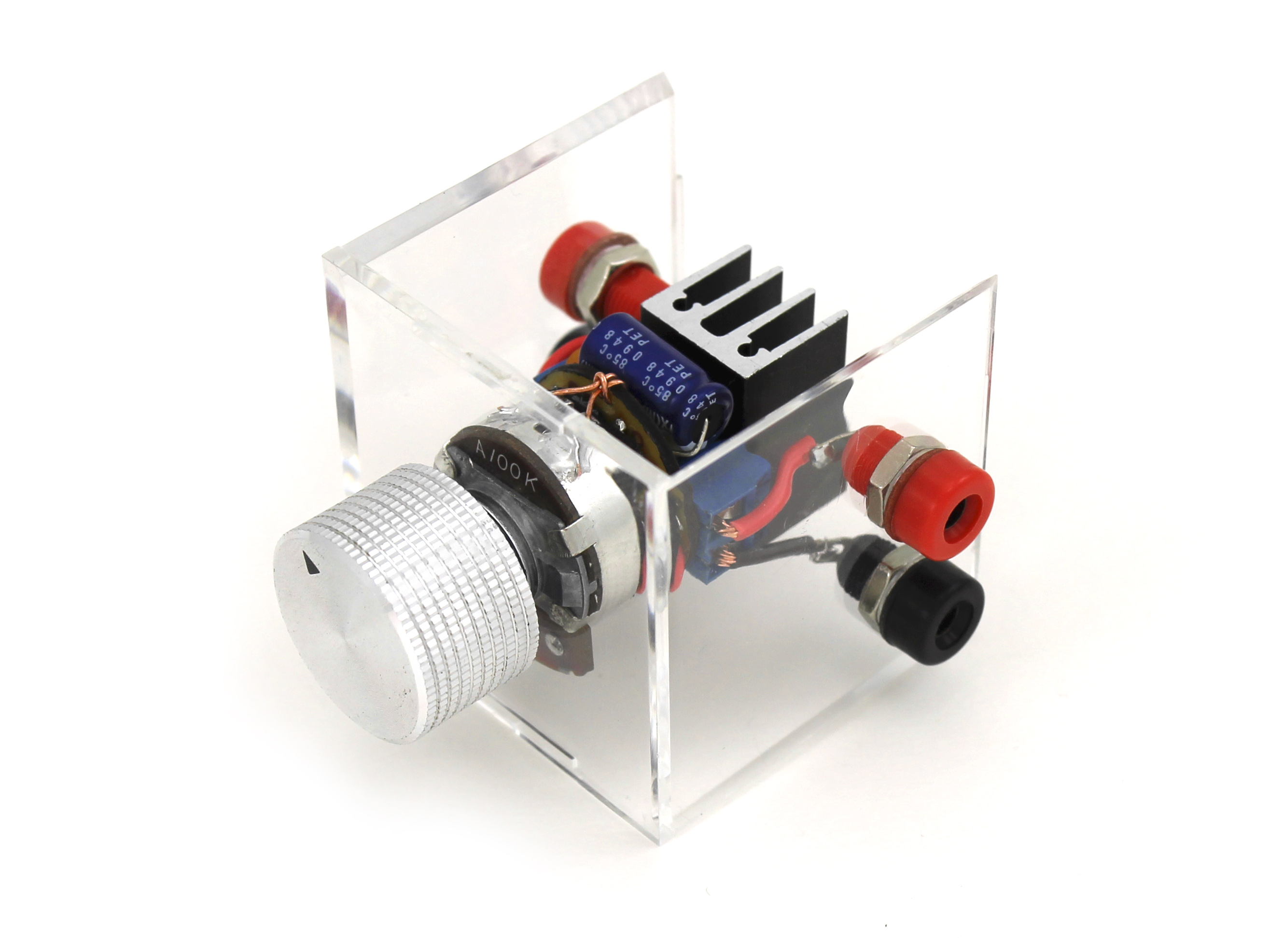
Enter the Dial-a-Speed, a DIY one-size-fits-most speed controller for small DC motors. It’s built in a compact physical package around a full-size potentiometer, includes built-in back-EMF protection, and has on-board screw terminals for easy motor and power connection. The Dial-a-Speed accepts 5-12V DC, can be easily panel-mounted in most enclosures, and will provide effective speed control of any continuous-rotation motor or fan in the RadioShack catalog as of this writing.
PRODUCT | VOLTS (DC) | MAX (RPM) | MIN (RPM) |
![]() |
9 / 12 | 11,030 / 14,300 | 176 / 795 |
![]() |
6 | 15,500 | 1,191 |
![]() |
7.5 | 15,900 | 1,259 |
![]() |
9 | 20,200 | 2,641 |
![]() |
5* | 17,900 | 2,462 |
![]() |
5* | 16,700 | 2,798 |
![]() |
12 | 6,640 | 115 |
![]() |
12 | 2,432 | 130 |
![]() |
12 | 2,611 | 100 |
How Does it Work?
This is a pulse-width modulation (PWM) speed controller, using a 555 timer IC wired in astable mode to control an N-channel power-enhancement MOSFET that actually switches the motor on and off. It is based on a circuit posted by Rick Bickle of the Dallas Personal Robotics Group, with minor modifications for use in a shared power supply configuration.
What does all that mean? Basically, instead of a continuous stream of current, the circuit sends power to the motor in little pulses, at a more-or-less constant frequency (around 50 times a second). The length of these pulses (aka their width) can be changed (aka modulated), which causes the speed at which the motor turns to change, too. The longer/wider the pulses, the faster the motor goes.

Square wave with 60% duty cycle. “Pulse width modulation” implies changing the duty cycle without changing the frequency of the underlying wave.
If you were to plot the voltage going to the motor against time, perhaps using an oscilloscope, it would look more-or-less like a square wave, illustrated above. When describing square waves, the amount of time spent in the “high” voltage state is called the mark time, and the amount of time spent “low” the space time. The duty cycle is a percentage expressing how much of each wave cycle is “mark time.” For example, if your pulses are coming 1 a second, and your mark time is 0.6 seconds, then the duty cycle is 60%. This circuit is cleverly designed to offer a wide range of control, and can produce square waves with duty cycles ranging from less than 5% to more than 95%, depending on where you set the dial.
I will be making one to use for my: http://www.instructables.com/id/ATtiny8545-POV-Display/
Made it. Didn’t work for me. I’m not sure if the 555 timer or MOSFET is bad or what. Building it for use in the Optical Tremolo 2.0 project for my guitar teacher. I used the instructions from Make, assembled it just like shown, and it just didn’t work. When I first finished it, it only showed maybe half a volt or less on the motor terminals, and the Vcc and Ground leads appeared to be shorted. But then it got weird. The next day, I tried it, and the fan worked, but the potentiometer had no effect. I tried again again the next day, and it worked fine. However, when the potentiometer was twisted all the way to what would be off, it ran the fan on full voltage. It worked though, so I made the optical tremolo 2.0 project, only to have it not work for me again. Yet again, the motor terminals only show maybe half a volt. Sent an email to the creator of the project close to two weeks ago, and he still hasn’t responded. I doubt he ever will. This project has probably been around too long for Make to comment on it or help me.
much the same problem here, less than a volt showing on the volt meter at the terminals. Did you use new mosfet and 555 ic? Guess I will try to learn to use my oscilloscope and follow the troubleshooting suggestions. Curious to know if you were able to finish your Tremolo 2.0 ? There are fan speed controllers available online for cheap that should work if all else fails. Id like to get mine going, spent a lot of hours building it.
Did you ever get your controller to work? Ive been trying a breadboard model with no sucess. Mike
I took a day off work to finish building the dial a speed speed motor controller for the optical tremolo 2.0 and the output voltage ranges from 0.17V to 0.77V, similar to what you mentioned in your post above. Unfortunately I don’t have a scope. Did you find a simple fix? My goal was to have it built for my dad for Father’s day, but it is not looking promising. The optical isolator and sensor head seem to be testing out okay. Thanks for any input. Joshua
Check polarity of your diodes.
So I live in Canada and I can’t find the heat sink on any Canadian sites. I’ve checked mouser, does anyone know if there’s a different one I can use, or somewhere else I can find that one?
Any heat sink that fits TO-220 should be fine. This one from Mouser ( http://www.mouser.ee/ProductDetail/Aavid-Thermalloy/581002B02500G/?qs=sGAEpiMZZMttgyDkZ5Wiuua5pzU5xE5ZX3Yy1QskXag%3d ) seems closest to the one used in this project.
I used one a local electronics repair shop had from old computers. Remember, it says it is probably not necessary though.
Hello. I built it, first on breadboard then on PCB. Both worked, however I noticed that PCB version ran the motor slower on max setting. The only difference was that I used SMD 555 on PCB version. To me it seems strange, but could that have had made the difference? If not does anybody have a guess, what could have done it?
Could you have the connections to the
Potentiometer upside down? Here is what went wrong for me…
A great and well described project. At first, upon completion, the dial-a-speed would supply power at full power and only reduce voltage slightly … .3-.5V at most. All visible soldering matched he pics, however, I discovered a lose green lead from the Pot was not connected and the black wire was going to pin 2 instead of pin 3. After this it worked perfectly.
http://www.hkprogolf.com/inc/print.htmlcheap nfl jerseys nike
[url=http://www.hkprogolf.com/inc/summary.html]cheap nfl jerseys paypal[/url]
What happened to the step by step instructions?
A great and well described project. At first, upon completion, the dial-a-speed would supply power at full power and only reduce voltage slightly … .3-.5V at most. All visible soldering matched he pics, however, I discovered a lose green lead from the Pot and the black wire was going to pin 2 instead of pin 3. Once these wires were connected to the correct pins it worked beautifully!!! Hope this helps someone. And thanks to Make and Sean Ragan
Hey! Can someone help me please?…. The circuit is great but I want to control a bigger motor….. 12v 1000 watts…. What parts I need to change? Thanks!
XAXAXAXAxaxaaxaxaaaaa
BUY A VARIAC the wattage would instantly melt any you make your self (from past experience)
The motor is powered up by a car battery
It is imperative to know your parts! Especially since sourcing them through Radio Shack, at this point in time, is an impossible task for some. Use the data sheets for your specific parts. My 12v fan did not work with this circuit until I increased the value of the C2 capacitor up to ~1.5uF. I would recommend an inverse log pot also for larger voltage motors/fans since they need a higher initial voltage to get spinning, you’ll turn the pot much less before the motor spins and then you’ll have a nice gradual taper for fine tuned control after the hump.
You seem knowledgeable; any chance you can explain to me what the purpose of the two diodes connected to the potentiometer is?
I bought a…
Dimmable CFL/LED bulbs (screw-base) Single-pole TTCL-100H-EE100W
http://www.lutron.com/TechnicalDocum…%20Dimmers.pdf
And a Original Magic Wand…
Power source: 110 – 120 volts electrical outlet Two speeds: ca. 6,000 / 5,000 vibrations per minute (on high / low setting)
10W (no load) Plug type: US polarized
http://magicwandoriginal.com/about-magic-wand-massager/
Can I use the dimmer as a control so slow it down, the Wand only has 2 settings and they are aggressive.
The dimmer I was hoping would create lots more variable in speed and intensity.
Will it damage the motor over time?
Thanks…
Can anyone tell me what the two diodes connected to the potentiometer are for? I think I understand the functions of all of the other components, but I don’t quite get why those two diodes are there.
as i wanted to start my lathe machine project, i found this article was so miracle but when i tested that circuit on the breadboard with my 12VDC motor powered by a 12V sealed lead acid battery, firstly, nothing changed when i turned the pot. Finally, my NE555 has been burst, one small piece rocketing flew straight up to the sky ^^. Do you have any ideas about my case?
ConfigureACCEPT
Privacy Overview
Necessary cookies are absolutely essential for the website to function properly. This category only includes cookies that ensures basic functionalities and security features of the website. These cookies do not store any personal information.
Any cookies that may not be particularly necessary for the website to function and is used specifically to collect user personal data via analytics, ads, other embedded contents are termed as non-necessary cookies. It is mandatory to procure user consent prior to running these cookies on your website.