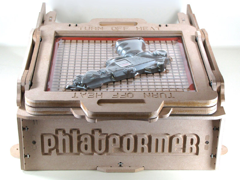
The Phlatformer is a hobby vacuum-forming machine that quick-melts 10″ square plastic sheets into form-hugging shapes. Originally built for R/C modelers to make identical, lightweight body parts, it has many uses; for example, I plan to form custom holders to display my raygun collection. The kit’s parts and thoughtful extras never skimp on quality, and include everything except a vacuum cleaner and a hot plate — I use a Rival S11P 11″ skillet from Wal-Mart ($20). The DVD build guide can be supplemented with the active forum at phlatforum.com, and although there are lot of parts, most of them are self-indexing and more or less impossible to assemble incorrectly.
What will the next generation of Make: look like? We’re inviting you to shape the future by investing in Make:. By becoming an investor, you help decide what’s next. The future of Make: is in your hands. Learn More.

Project Steps

Prepare waffleboard

Use rubbing alcohol and a paper towel to clean out the groove around the edge of the waffleboard. The idea is to remove sawdust remaining from the machining process. Later, the red rubber seal will be installed in this groove.

While you’re at it, clean the rabbet in part #8, as well. Later, the grey foam strip will be installed in this recess.

Turn the waffleboard grooves-side-down and install two separators, as shown.

Count six holes across from one corner, and 4 holes down.

Locate the spacers as shown in the illustration, trace around them, and apply glue. Don’t get any in the vacuum holes.

Apply glue sparingly around the edge of part #3. Align the outside edges of part #3 with the waffleboard and press down. Verify that the two pieces are flush on all four sides.

Assemble vacuum table

Tape eight square nuts into the square recesses on the underside of part #4, to hold them in place during assembly. Turn part #4 over.

Apply a bead of glue to the exposed side of part #3, and to the underside of the separators from step 1. Turn the waffleboard over, align one corner with the screw holes in part #4, and press them together.

Start a screw in one of the corner waffleboard holes and run it through parts #1, #3, and #4 until it engages the threads in the nut. Tighten the screw until the head is flush with the bottom of the groove.

Install screws through the remaining seven holes. Do the corners, first, then the center hole along each edge.

Install vacuum pipe flange

Apply a bead of glue to the octagonal flange (part #19).

Fix part #19 into the corresponding recess on part #4, and push it down firmly. Wipe up any glue that squeezes out of the joint.

Set the assembly aside to dry.

Prepare heat shield

Be careful! The edges of the foil tape can be quite sharp, especially where it’s freshly cut.

Cover the underside of part #6 (the side with the rabbeted edge) with six 11″ strips of foil tape. Overlap the strips by about 1/8-1/4″.

Excess tape can be trimmed flush with a razor knife or just folded over. Tape can be buffed smooth using the peeled-off backing.

Laminate the two handle sections (pieces #5) together with a bead of glue between, lining them up as well as you can by eye.

Poke small holes through the tape over the handle screw holes using, e.g., a Phillips-head screwdriver.

Align the handle with the slots in the top of the heat shield (note slots on one side are smaller) and seat the handle in the slots. Use some pressure and be patient.

Slip the square nuts into the slots in the handle, insert a screw from the underside of the heatshield, and start the screws into the nuts. Tighten down with a screwdriver to secure the handle.

Vacuum plumbing connections

Locate parts P1, P2, and P3. Press-fit short section P1 into elbow P2. Press-fit pipe section P3 into other opening of elbow P2. Set aside.

Fit pipe section P5 onto universal shop vac adapter P6, as shown. This will be a loose fit.

Seal the joint between pipe section P5 and universal vacuum adapter P6 with a strip of aluminum tape, as shown. Set aside.

Cover lower frame with foil

Position part #7 on a table top with the recesses down. Cover the top side with four strips of foil tape, leaving some excess on the outside edges. Buff the tape smooth using scrap tape backing.

Flip the frame over and trim around the outside edge with a razor knife.

Cut the foil out of the four cross-shaped slots on the thick edge of part #7.

Assemble lower frame

Position part #7 foil side down, and part #8 recesses side up.

Apply a bead of glue around the surface of part #8, making sure to get a bit more in the thicker area between the cross-shaped-slots.

Join the exposed surfaces of parts #7 and #8, aligning the inside edges as best as possible.

Glue one of the two magnets into the round recess in part #8.

Set the lower frame assembly aside.

Assemble upper frame

Position part #9 with the recesses down. Part #10 is the same on both sides, so it does not matter which side faces up.

Apply a bead of glue to part #10, as shown.

Glue the exposed surfaces of parts #9 and #10, as before, aligning the inside edges of the frame.

Make sure the cross-shaped slots on the outer edges are also aligned.

Cabinet sides

Slot part #13 into parts #12A and #12B, as shown. Parts #12 should be positioned with circular recesses facing each other, close to the tabletop, inside the box.

Position part #11 with the text upside down, and slot the tabs in parts #12 into the slots in part #11.

Insert square nuts into slots in parts #12 and tighten screws through corresponding holes in nameplate (part #11). Do not overtighten.

Flip the cabinet assembly over.

Waffleboard installation

The Phlatformer logo text should now be right side up.

Locate the waffleboard assembly and slot it into place on the exposed cabinet tabs as shown.

Use eleven smalls square nuts and matching small screws, as before, to secure the waffleboard to the cabinet sides.

Do not overtighten. If any parts are visibly bowing, loosen the screws.

Install levers

Insert a small nylon spacer into the hole on the notched end of each of the four levers (parts #14).

Insert a large nylon spacer into the hole on the round end of each of the four levers (parts #14).

Insert the truss head bolts into the circular recesses in parts #12, with the threads protruding outside the cabinet volume. Tape the bolt heads in place temporarily, inside the cabinet, to keep the bolts from falling out.

Slide a small washer onto each of the exposed bolts.

Position one lever (part #14) over each exposed bolt end as shown, followed in each case by a second washer.

Install exterior cabinet sides

Slot exterior cabinet sides (parts #15) over the levers, bolts, and interior cabinet sides (parts #12) as shown.

Insert a large square nut in each of the two square recesses on each of the two exterior cabinet side panels (parts #15) you just installed.

Inside the cabinet, remove the tape covering each bolt head and tighten the bolt into the corresponding square nut.

Secure exterior cabinet sides (parts #15) to parts #13 and #11 using small square nuts and screws, as shown.

Install cabinet bottom panel

Flip the cabinet over so that the logo text is upside-down.

Position part #16 with the screw countersinks up, align the tabs in front and in back, and snap into place as shown.

Insert square nuts into the mating slots beneath each of the nine countersunk holes in part #16.

Tighten nine bolts through part #16 into mating square nuts in cabinet sides below. Do not overtighten.

Install lever flanges on lower frame

Install parts #17A and #17B on the sides of the lower frame assembly, as shown, with the recesses facing the inside of the frame.

The rounded end of parts #17A and #17B should be closest to the end of the frame with the magnet.

Position a square nut in each of the four slots in the lower frame assembly to mate with screws driven through parts #17A and #17B.

Tighten screws through parts #17A and #17B into the square nuts positioned in the frame assembly. Do not overtighten.

Install weatherstripping in lower frame

Feed weatherstripping from the roll and tack it down lightly in one corner of the rabbet in the frame assembly.

Gently unfurl the weatherstripping, without applying tension, lightly tacking it in place until one side of the rabbet is completely filled.

Use a razor knife to cut the weatherstripping flush with the end of the rabbet, and go back and press it down firmly along its length.

Repeat for the remaining three sides of the rabbet.

Attach frame assembly to levers

Position lower frame assembly on top of waffleboard, with the magnet up and out over the nameplate end of the cabinet, aligning frame flange holes with holes in lever ends.

Insert bolts from inside frame flange toward outside of unit, passing each through the flange itself, first, then through a flat washer, then through a lever bearing, and then through another flat washer. In other words, flat washers should be interposed on both sides of the swinging levers.

Position parts #18A and #18B over the exposed bolt ends, as shown, with the square recesses facing out.

Position square nuts in corresponding recesses in parts #18A and #18B, and tighten down mating bolts using flat-head screwdriver. Do not overtighten.

Test the swinging operation of frame assembly. Loosen bolts slightly to free operation, if necessary.

Install frame hinges

Position upper frame assembly (parts #9 and #10) on top of lower frame assembly with hinge mounting slots aligned. Surface recesses at hinge slots in upper and lower frame assemblies should be facing each other.

Insert a screw through each of two holes in one “flap” of each of the two hinges. The screw heads should be on the pin side of the hinge. Loosely thread a small square nut onto each screw.

Slip an assembly of one hinge, two screws, and two small square nuts into each pair of slots in the upper frame assembly, as shown. Adjust the vertical position of the hinges to center the pin over the joint between upper and lower frame assemblies. Tighten down the screws.

Raise the frame assembly on the levers and insert screws and nuts as needed to secure the other “flaps” of the hinges.

Adjust and tighten as necessary to keep each hinge pin centered over the joint between upper and lower frame assemblies.

There may be a small space between the upper and lower frame assemblies when the hinges are properly aligned. This is OK.

Install upper frame magnet

To make sure both latch magnets are installed with the poles correctly aligned, set the loose magnet on top of the installed magnet in the lower frame assembly.

Apply a generous dollop of glue to the upper side of the loose magnet.

Lower the upper frame assembly on the hinges. The surface of the magnet bearing the wet glue should mate with the corresponding recess in the upper frame.

Allow the glue to dry. If you don’t want to stop work to wait for it, open the frame and temporarily tape the magnet in place.

Install rubber seal

Unfurl the pre-cut rubber seal and peel back about 1/3 to 1/2 of the adhesive backing. Position the free end, adhesive side down, in the groove around the waffleboard, with the end of the seal exactly centered over the middle screw head on the nameplate side.

Work around the four edges of the waffleboard, peeling off the adhesive backing and gently tacking down the seal, in the groove, as you go. The pre-notched corners should line up with the corners of the groove fairly well. Don’t push anything down firmly yet.

Once you’ve worked back around to the starting point, you may find that you have a bit of slack left over. Don’t cut it off. Instead, butt both ends of the seal together, which may cause a “hump.”

Work backwards around the groove, flattening the hump and working the seal firmly into the groove.

Sand the front edge of the waffleboard

When operating the frame assembly, You may find that the front edge of the waffleboard sticks, a bit, against the underside of the frame. If so, follow this procedure.

Raise the frame, on the levers, so the front edge of the waffleboard is clear for work.

Use a small sanding block to break the sharp edge on the waffleboard nearest the front of the unit.

Also sand the corresponding edge on the underside of the raised frame.

Continue until the frame can be raised and lowered without any interference between these edges.

Install the plumbing

Locate the P1-P2-P3 assembly from step 5. These should be press-fit together, and there really is no need to glue them.

Put a bead of glue around the rim of part P1, in this assembly, and install the assembly in the Phlatformer, with the glued edge of P1 mating with the recess in Part #19, as shown. Wipe off any excess glue.

Locate the P5-P6 assembly and decide which side of the Phlatformer you want to attach the vacuum from. This decision will depend on whether you want to operate the Phlatformer in a left- or right-handed orientation, and whether you want the vacuum hose to run out the side closest to you or the side furthest from you when the unit is in operation.

Press fit P4 onto P3. Make sure the elbow P4 is facing in your preferred direction.

Slide the P5-P6 assembly through the one of the two holes in the cabinet sides, aligning the four bolt holes in P6 with the corresponding holes in the cabinet. Use the remaining four bolts and large square nuts to secure P6 to the frame.

Finishing touches

If you like, the unused hole in the Phlatformer frame can be permanently sealed using the bundled circular plug (Part #20). Just run a bead of glue around the edge, set it in place, wipe off the excess glue, and align the plug flush with the cabinet wall. Allow the glue to set.

Use the four black wood screws to mount the Phlatformer to your workbench through the holes in the unit’s “feet.”

If you like, you can paint the Phlatformer. The excess tabs protruding through mating parts can be sanded flush with a small sanding block before painitng.

Use: Heating the plastic

Position a suitable heat source, such as the hot plate shown, beside the Phlatformer so that it is directly under the frame in its “heating” position.

Install your vacuum hose in P6.

Turn the vacuum cleaner on and plug it into the foot switch. Plug the foot switch into the wall and verify that it turns the vacuum on when you operate it.

Load a piece of 12″ square plastic into the frame as shown.

Plug in the hot plate and turn it on. Put the heat shield in place over the frame. Position a suitable form on the molding table.

Use: Pull the form

Watch the underside of the plastic sheet. When it begins to droop uniformly, remove the heatshield and lift the frame, on the levers, moving it towards the molding table.

Before seating the hot plastic over the mold, activate the vacuum using the footswitch.

Keep your foot on the vacuum until the plastic has pulled down tightly around the form and has cooled down enough to harden.

Open the frame and remove your vacuum-formed part!