Let’s talk about the matrix! In this article, we’re going to learn how to make and read touch-sensitive panels using matrices and conductive textiles. This might sound a bit intimidating, but we’ll take it step by step and understand the basic concepts. These touch panels can be used with a microcontroller to control all kinds of projects, or with your computer! 


First of all, matrices aren’t that complex. A matrix is just a series of rows and columns — basically a table. You can pinpoint a location in the matrix by finding the intersection of rows and columns, for example location 2b in Table 1. 

Table 1: Simple coordinate matrix

This concept is used widely in touch pads and panels, because you can easily use it to figure out where a user’s fingertip is physically located using the coordinate system. These days, most touchscreens use capacitive touch or other modern tech to distinguish greater detail, sensing the fingertip by tiny changes in electrical field.

Figure A
This project is from Make: Magazine volume 87. Subscribe to get more

But some of the earliest touchscreens, like the Nintendo DS, use resistive touch technology to sense the fingertip by pressure: conductive rows and columns of a grid are separated by a semi resistive barrier, so that when they’re pressed together, a row and column are connected and you can pinpoint that place on the grid (Figure A ). In a manufactured resistive touchscreen, a transparent conductive material called ITO (indium tin oxide) is applied in a very thin and dense grid to the screen panels so the screen is still visible. 
You can also find matrices as common components in DIY electronics, such as an LED square matrix, 7-segment display, or button array. While a touchscreen works by keeping conductive traces apart to sense coordinates, an LED matrix works by sending coordinates from a computer program — connecting the positive and negative ends of an LED through rows and columns to light up a specific light. I really like this matrix concept, because it can be used to make really interesting and complex interactions with super simple tech!


There are touch matrices everywhere — think of every screen to buy groceries or transit tickets, or to use your phone, computer, or tablet. But resistive touch technology is a bit out of date, so you’ll probably only encounter it in more frustrating scenarios. Modern touch technology uses capacitive touch, so it can have multi-touch inputs and much more precision. 


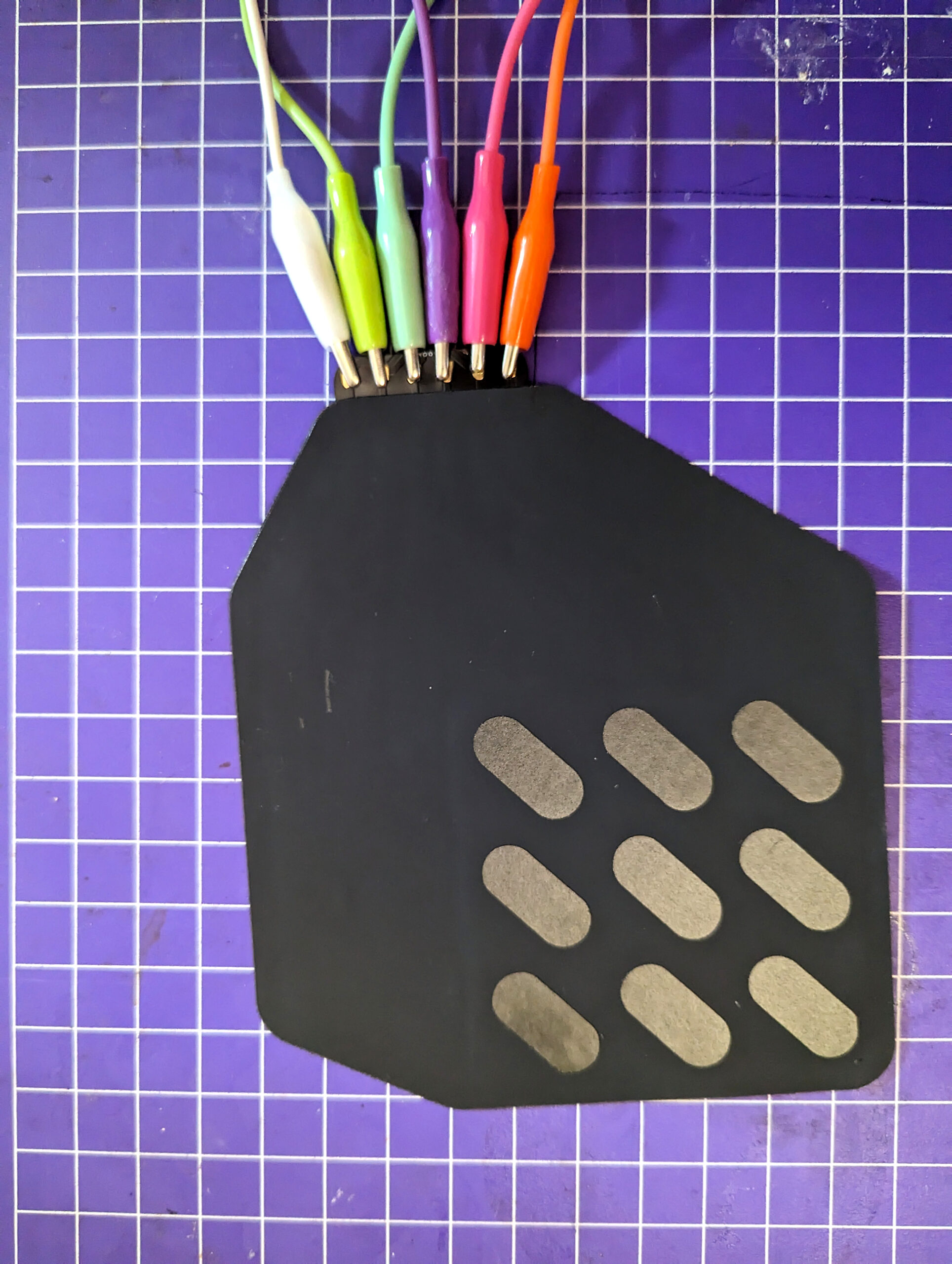
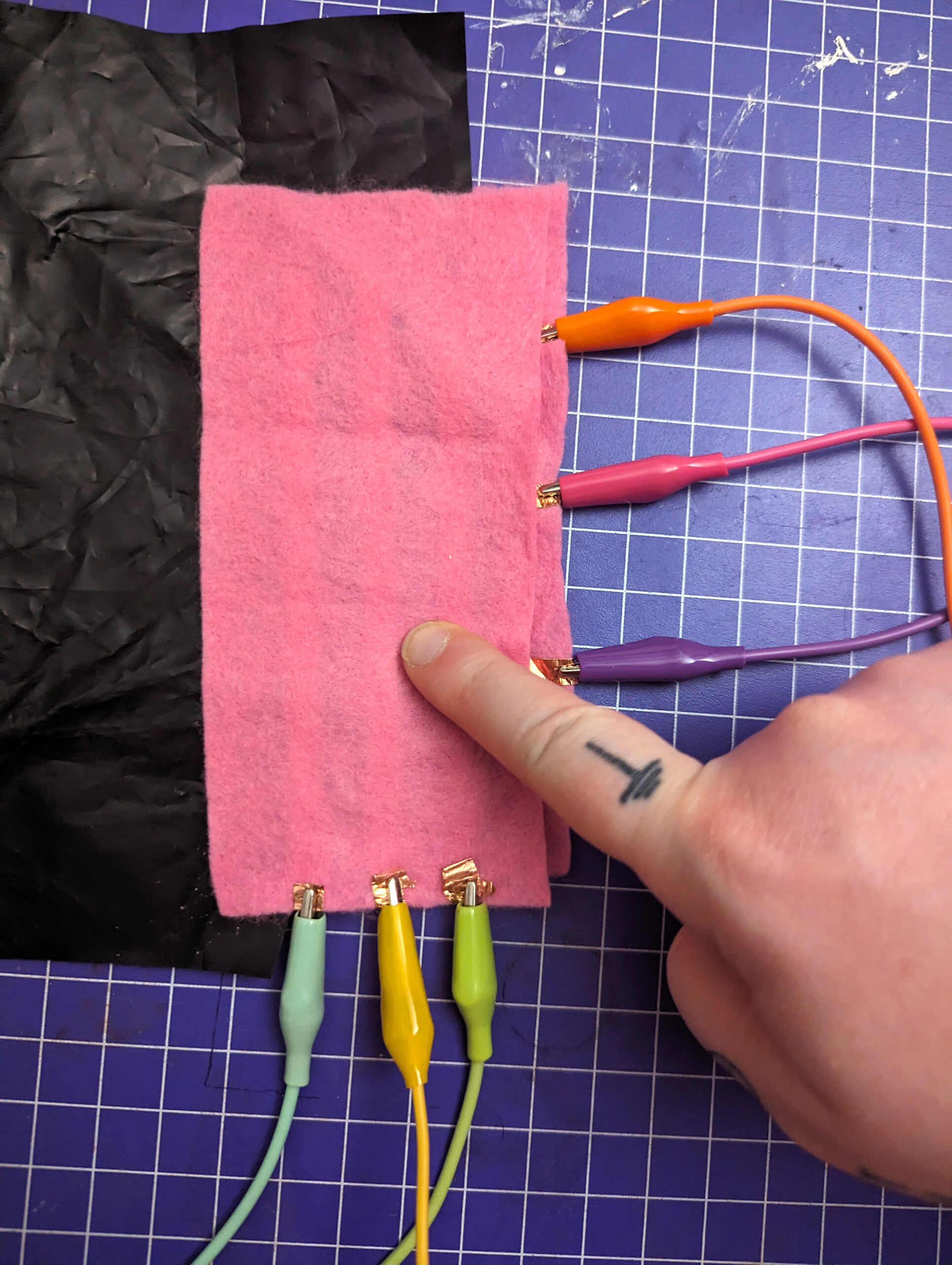
In order to make a “soft” touch panel, we’re going to use a few concepts that I explored in my previous columns. Like our soft pressure sensor from Volume 86, you’ll be using both resistive and conductive materials to make a “sandwich.” (I’m continuously realizing that most electronics projects I share here are described as sandwiches!)


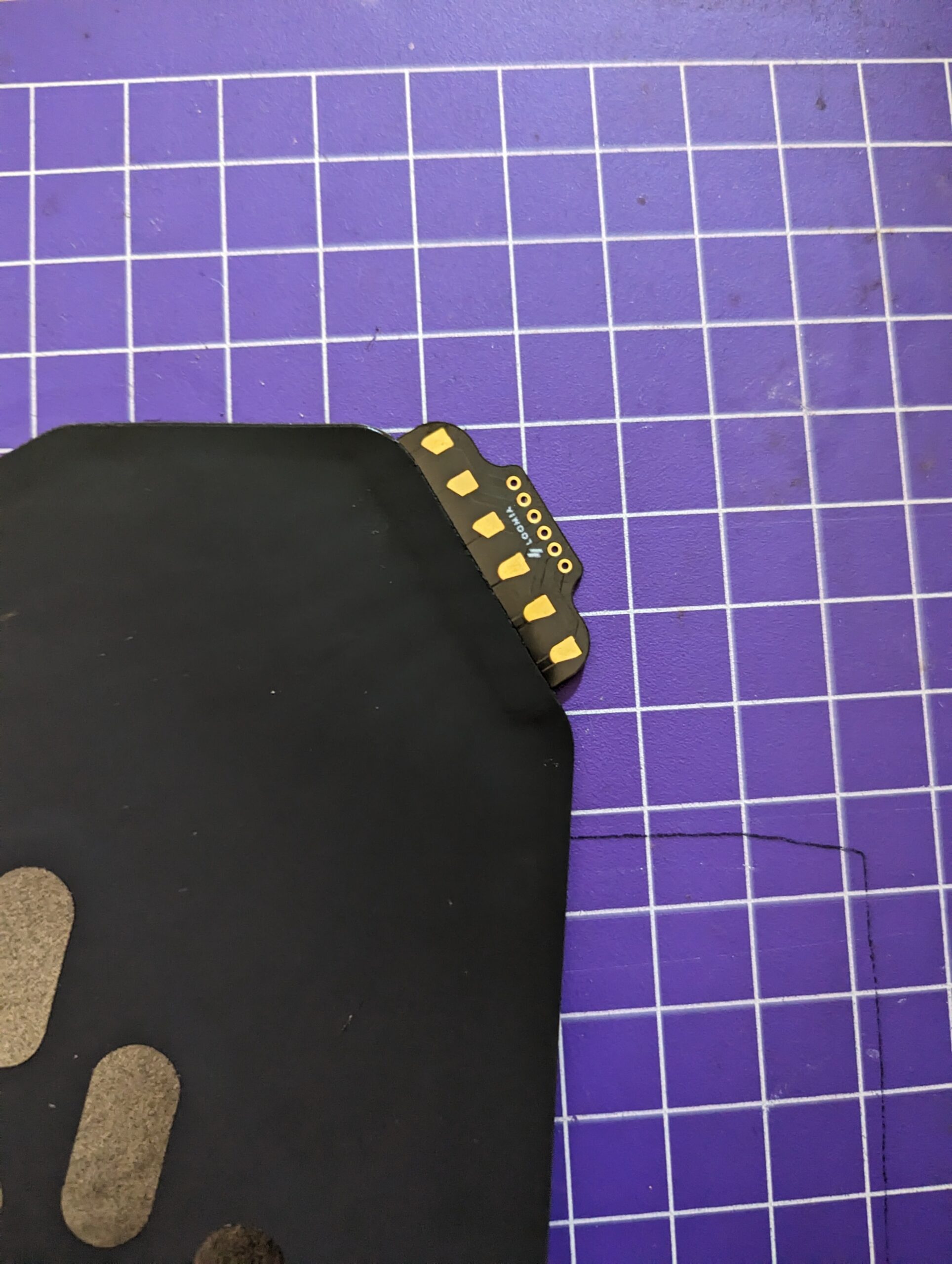
Essentially, you’ll arrange conductive traces in rows and columns which are separated by a semi-conductive material. When the intersection of the rows and columns is pressed, the resistance between the traces changes, and you can detect the physical location of the touch. Depending on the density of your grid, you’ll get more or less accuracy. Let’s start simple. 

Project Steps

Prepare your matrix 

Figure B

You can either use a pre-made touch matrix, like Loomia’s Mega Pressure Matrix (Figure B),
or make your own. Loomia makes a variety of amazing soft surface interfaces for prototyping. Their touch matrix panel is made of a sandwich of materials similar to what we will make here, but prefabricated and very reliable. The back of the panel also has a super handy adhesive coating to mount onto anything. And it’s got big connection pads for easy prototyping with alligator clips, with matching through-hole pads you can solder permanently when you’re ready (Figure C).

Figure C

There are a series of other cool Loomia tools, like connectors, buttons, and even a heating panel (loomia.com/shop), but that’s for another article.
If you’re making your own matrix, first you’ll have to design your grid. An easy way to start is a regular grid with about 2″ spacing between rows and columns. Like most DIY electronics, especially textiles, there’s always the temptation to go small for the first try, but giving yourself some space will make the process easier.

Lay out the rows on one piece of material and the columns on another. Make sure they are straight and overlap properly if you place them on top of each other. It’s helpful to make a template with a marker first, and lay your traces on top (Figure D). Let’s start with a 3-row by 3-column piece, making 9 intersections.
Make sure the rows and columns go to the edge of your material on at least one side. Place a piece of velostat (Figure E) fully separating both grids (Figure F) and then sew it together with nonconductive thread into a delicious matrix sandwich. Rows and columns should never touch.
Attach an alligator clip to one end of each row and column. Connect the opposite clip to a jumper wire that you’ll connect to your Arduino. If you’re using a Loomia matrix, you can cover the through-hole pads with tape (or snip them off) and attach 6 alligator clips (Figure G).

To wire the circuit, you must connect each row and column correctly. We’ll make all the rows Analog, and all the columns Digital. I’ve used an Adafruit Flora because it’s made to attach alligator clips, and it’s round which is great for soft circuits (Figure ). But this concept will work with any similar microcontroller; just check your pinout diagram to find digital and analog pins (Figure ).

Set up your code

You can find the full, commented Arduino code at on Github. I’ve adapted and modified this code from Kobakant’s original resistive touch concept. It’s a bit hard to parse, so let’s break it down.

First, we will initialize variables we’re going to use and define the number of rows and columns so Arduino knows how to cycle through them.

define numRows 3

define numCols 3

Next we add the names of the pins to our rows[] and cols[] arrays — make sure to consult the pinout diagram! — and then create a two-dimensional array to hold the incoming variables so we can read the whole matrix at once:

int rows[] = {A10, A9, A7};
int cols[] = {3, 2, 0};
int incomingValues[numRows][numCols] = {};


In our setup function, we cycle through all the rows and set them to INPUT_PULLUP.

Note: If your controller doesn’t have an internal pullup resistor, you can add an external one by following these instructions

We will make all of the columns INPUT as well and start the serial monitor:

void setup() {
    for (int i = 0; i < numRows; i++) {
        pinMode(rows[i], INPUT_PULLUP);
    }
    for (int i = 0; i < numCols; i++) {
        pinMode(cols[i], INPUT);
    }
    Serial.begin(9600);
}


This is where the code gets a bit tricky. We’re going to fill every element in the second array by cycling through rows and then columns. We can see what column we’re in because we’ve set it to OUTPUT, and then cycle through all the rows inside of it. This way we don’t need as many pins, because we are isolating each row.

Figure J

Upload this code (Figure J) to your Arduino and test it out! Have a look in the serial monitor to see the output.


Test your pressure touch matrix

Figure K

At the end of the code are two functions that can help us debug. You’ll notice a grid of numbers in the serial monitor. The function printGrid cycles through all the rows and columns and prints them here as a number. When you push a button, or a copper tape intersection (Figure K), the value of that entire row will be lower, but the exact button location will also be clear as the lowest value.

Figure L

In order to find the lowest value, we can use the findActiveButton(); function (Figure L) . This function cycles through all the incoming values and determines which is the lowest. If any of them are under 100, then it’s likely a button is being pressed. If you made your own touch matrix, it’s possible these numbers are different. You can use a calibration function to determine a baseline value (see Volume 86, pages 96–97), or just check manually what the values tend to be when something is pressed.
If you’re getting erratic readings, it’s possible that your resistive material isn’t fully separating your conductive rows and columns, or that a connection isn’t being made somewhere. Double-check your sewing and wiring.
To give your touch matrix a different feel, you can experiment with placement and even integrate the soft pressure sensors I shared in Volume 86, “Squish It! How to make a DIY pressure sensor.”

Conclusion

Integrate and Install!

Now that you’re able to read your resistive matrix, you can make it do things! There are a number of ways of doing this.
• You can use the different locations on your touch matrix to change an LED strip’s patterns or colors, or to trigger a different interaction.
• You can connect your touch matrix to a computer and control a web page, game, or interactive art.
• You can use platforms like Processing to read the values through the serial monitor and trigger actions there.

It’s fun to integrate these soft matrices into clothing that you can control in an organic way. I’ve mounted my Loomia matrix to my bag so I can control my wearable LEDs!