In early 2011 my robot club, the Dallas Personal Robotics Group, was looking for a way to help our beginning members build up their skills. To this end, we produced a series of lessons covering 5 topics needed to make a simple, programmable robot: making PCBs with the toner transfer method, programming ATtiny microprocessors, laying out circuit boards using KiCAD, using Inkscape to design robot parts, and programming state machines. Videos of these lectures are available on DPRG’s website.

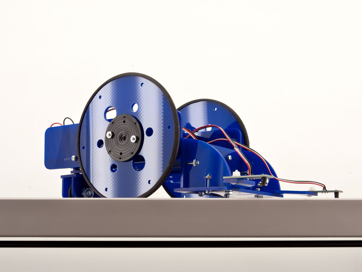
The Tiny Wanderer is the starter DIY robot model we designed to support the series. It uses the unintimidating ATtiny85 chip, which is less complex than larger chips, and the new kit version shown here lets you easily swap in an Arduino.

The chassis, inspired by the now-discontinued Oomlout SERB, has benefited from constant modification and tweaks by DPRG members. Its two IR LED/sensor proximity “feelers” were originally designed to let the bot wander around a tabletop without falling off, but they can be repurposed for obstacle avoidance and line-following. (Another successful mod added 64-slot encoders on the wheels, for dead reckoning.)

SVG and PDF cutout templates

Download the Code

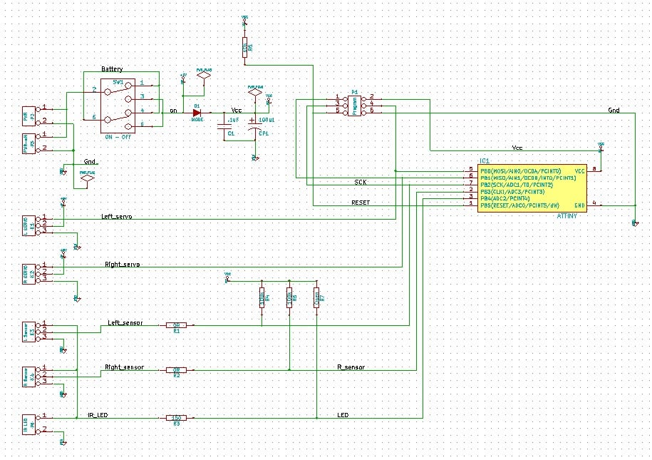
Circuit Board Layout files

Wiring Check Tables

Before inserting the ATTiny85 into the socket on the controller board you should make some simple ohm meter checks using these tables.

Here are some additional mods that give Tiny completely different personalities:

I hope the fun we’ve had with Tiny Wanderer will be shared with other hobby roboticists and makers around the world.

Project Steps

Build the Chassis.

Peel the protective plastic off all acrylic parts. Insert the rubber grommets packaged with the servos into the 4 servo mounting holes. Use four #4×3/8″ screws to attach each servo to one of the 2 acrylic side pieces, with the shaft aligned with and on the same side as the etched guideline. With the motors installed, align the side pieces next to each other and make sure they match up.

See http://makeprojects.com/v/29 for more photos identifying all the acrylic kit pieces.

Fit the 2 acrylic axle holders into the bottom of the truck piece. Anchor each one with a nut in its cross-shaped cutout, screwed onto a #4 screw threaded through a washer from the top of the truck.

Fit the O-ring around one of the skateboard bearings. This will be the rear caster’s wheel. Mount it between the axle holders, with a large acrylic washer on either side, on a 5/16″×1″ bolt secured with a matching nut.

For the caster’s swivel mount, run four #4 screws through 4 small metal washers, then through the 4 mounting holes around the rear caster hole in the large acrylic base piece. Drop the bearing holder (the acrylic square with the larger center hole) over the 4 screws. Drop the bearing into the holder, then drop 4 small acrylic washers onto the screws. Finally, drop the bearing retainer (the square with the smaller hole) onto the screws and over the bearing. Secure with nuts.

The metal washers provide clearance; without them, the caster will hit the screws.

Attach the side pieces to the top of the base by fitting 4 nut/bolt pairs into its cross-slots, as in Step 1. Use 2 more nuts and bolts to join the tops of the side pieces to the crossbar piece.

Tweezers help to hold the nut in place while you start the screw.

Assemble the sensor tray from the sensor shelf, sensor shelf riser, 2 sensor shelf brackets, and 6 nut, screw, and washer sets. As with the other acrylic pieces, fit the tabs into the slots and secure by twisting the nuts down on the bolts in their cross-slots. The sensor shelf will act as a base for attaching the robot’s sensors.

Attach the sensor tray to the front of the chassis with 2 screws.

Attach the caster holder to the caster swivel mount with the remaining 5/16″ bolt and matching nut. Fit 2 large acrylic washers over the bolt between the underside of the swivel mount and the top of the caster holder, so the caster can turn without mounting hardware getting in the way. The inner race of the horizontal bearing should be clamped between the large bolt head and the 2 acrylic washers.

You may have to temporarily loosen the screws to get the bolt to fit through the caster assembly so that the bolt’s head is captured by the wheel supports.

Fit the tires and hub.

For each of the 2 tires, cut a 12¾” length of window screen spline. Use a seam ripper to puncture each piece about ¼” from one end. Slit the spline along one edge, going almost its entire length, but stopping when the seam ripper point shows at the other end.

Drop a dot of super glue onto a piece of thick paper. Run your finger down the slit to make sure it’s not twisted, then align the 2 ends and dip them into the super glue. Hold the ends together for 20 seconds; they should stick together. Put the tire aside for at least 15 minutes.

Use the seam ripper to slit the joint area, making the slit continuous. Starting with the joint, place the tire onto the wheel, working it around the rim a little bit at a time.

Place a pencil through the center of the wheel and roll it on a table to seat the tire. Use fine sandpaper to lightly sand the glue joint. Be careful — you only want to remove excess glue.

With each circular servo horn, center it under a wheel with the horn hub protruding through. Rotate the horn until you see 2 of its 4 injection-mold marks through each of the wheel’s slots. Mark the horn through the 2 slots with a sharp pencil. Drill two 7/64″ holes into the horn where the mold marks intercept your lines.

Use two #4 screws and nuts to attach a horn to each wheel, and mount the wheels on the servo axles using the small screw that comes with the servos.

Separate the PCB into 3 boards — the controller board and 2 sensor boards — by splitting it along its 2 scribe lines. You may need to deepen the scribe line between boards with a utility knife before separating them.

Cut the 8-pin female header into two 3-pin headers by cutting through the fourth and fifth pins. Sand the cut edges smooth.

Populate the board with the components as marked, starting with the shortest ones (resistors and diode) and working up to the tallest. Route the battery holder’s leads through the strain relief holes before attaching. Make sure the large capacitor’s polarity is correct, with the lead near the band marked with negative signs (–) opposite the hole marked (+). The female headers go into the locations marked “Sensor R” and “Sensor L.” Do not place the chip into the socket yet.

Use a multimeter to check all connections, following the wiring-check tables at http://makeprojects.com/v/29. If everything checks out, plug in the chip with its pin 1 near the switch, and its notch next to capacitor C1.

The wiring tables list all the pairs of points on the board that should have continuity or a specified resistance.

After any work on the circuit board, perform the checks again before you plug in the chip. Before checking, disconnect the servos and sensors from the controller board and turn the power switch off.

Assemble the sensor boards.

Plug a phototransistor and an LED into each sensor board, orienting the small flat on the side of the plastic lens (the LED’s cathode or transistor’s collector) as indicated on the board. “D” marks the LED’s position and “Q” marks the phototransistor.

Fit the 1″ length of heat-shrink tubing over a phototransistor so that its edge touches the board, then cut it off just above the plastic lens. Similarly fit and trim a piece over the other phototransistor. Do not heat the tubing.

Cut the 3-wire ribbon cable in half. Strip and tin all ends of both pieces. For each, solder one end to a 3-pin male header and the other to a sensor board, with the red wire in the location marked “1.”

Plug the cables into the female sockets on the controller board, connecting the red wire to the sides marked “1.”

Make the sensor arms.

The 2 sets of Tiny Wanderer sensor arms work with 2 different behavior programs: cliff-sensing (for wandering an empty tabletop) and object avoidance. See http://makeprojects.com/v/29 for a third sensor arm design, for line-following behavior.

For the cliff-sensing configuration, use zip ties to attach the sensor boards to the shorter of the 2 pairs of acrylic sensor supports, and bolt the arms to the sensor tray with the phototransistors and LEDs pointing downward.

For the object-avoidance arms, first make a bending guide by cutting a 100° corner on a scrap of wood. Mark each of the longer acrylic sensor supports 1¾” from its long end, warm it with a heat gun or by holding the heating element of a soldering iron near (but not touching), and then bend it over the guide.

Zip-tie the sensor boards to the object avoidance arms, then bolt the arms to the tray, angled slightly inward to avoid a blind spot in the center.

Program the ATtiny85.

Disconnect the servos from the PCB; you can leave the sensors connected. Plug your AVR ISP programmer between your computer and the onboard 2 x 3 header, with the pin marked “1” connected to pin 1 of the cable (marked with a triangle on the plug and a red wire).

When the two LEDs on the AVRISP mkII programmer turn green, the programmer is ready for use.

There are several tool chain options for programming AVR chips, but a good choice for beginners is to combine Atmel’s AVR Studio 4 with the open-source WinAVR.

Download and install WinAVR and AVR Studio 4 (search “AVR Studio 4” at http://www2.atmel.com/) and install with all defaults. You will need to register on the Atmel website before downloading the AVR Studio 4 installer.

Some have reported an issue of AVR Studio 4 installer freezing after selecting “Install”. A proposed work-around is to open Task Manager and end the task “Rundll32.exe.” The author has not experienced this issue.

Atmel now recommends their newer AVR Studio 5, which has some nice features, but is larger and more complex than version 4.

Launch AVR Studio 4. Click the “New Project” button at the top of the Welcome screen, then select “AVR GCC” for the Project Type, to specify the gcc compiler, for project code written in C. Give the project a name (“TW_tabletop” here), then uncheck “Create initial file” and check “Create folder.”

Create a new folder named “AVR” in My Documents, select that location, and click “Next.” In the next popup, select “AVR Simulator 2” as the Debug platform and ATtiny85 as the Device. Click Finish.

Download the Tiny Wanderer code examples from http://makeprojects.com/v/29, or else use your own code. Each program will consist of a .c and .h file, for the C source and headers. Copy or move these files to the project directory created in step 7c. For example use tinywanderer_edgeDetect_version2b.c and tinywanderer_edgeDetect_version2b.h, for the tabletop edge detection program.

Each project that you program into the Tiny Wanderer will have different .c and .h files. Be sure to use the appropriate .c and .h files for your project.

Open the project AVR GCC pane, right-click the “Source Files” folder, select “Add Existing Source File(s)” and specify the project’s .c file. Do the same for the project’s .h file after right-clicking on the “Header Files” folder.

Double-click both project files in the AVR GCC pane to open them up in the editor. Right-click Project → Configuration options menu item, select “Custom Options” at the left of the popup, In the Custom Options pane, uncheck “Use AVR Toolchain” box and add the locations for avr-gcc.exe and make.exe. The default locations for these will be C:WinAVR-20101001bin and C:WinAVR-20101001utilsbin, respectively. Click “OK”.

This is where you connect AVR Studio 4 to WinAVR, installed earlier. These instructions apply to AVR Studio 4.19 (build 760). This final version differs from previous versions of AVR Studio 4.

Now you can edit your program. To build the project for uploading to the ATTiny85 chip, select the “Build Active Configuration” icon on the tool bar or push F7. You will either see a successful build message or a list of errors for debugging.

After a successful build, connect your programmer to the Tiny Wanderer PCB board and click the “Display the Connect Dialog” icon on the toolbar. Turn the power switch on and make sure the robot has batteries. Select your programmer and click “Connect…”

Click the small “Connect to the Selected AVR Programmer” icon in AVR Studio’s toolbar. Click “Read Signature” in the resulting popup and wait for the “Leaving Programming Mode” message at the bottom.

Click the Program tab at the top, and wait for the path of the compiled HEX file to appear under the “Flash” subheading. Once it appears, click “Program” to upload it to the ATTiny.

If you change projects, the HEX file path will not change. You must change this path to the new project’s file.

Turn off the power to the board, unplug the programmer, and re-plug the servos.

Congratulations! You have reprogrammed your AVR microprocessor.

Make the finishing touches.

Bolt the controller to the chassis with the battery wires pointing rearward. Use small acrylic washers as standoffs under the board. Add velcro for holding the battery case onto the rear of the base.

Plug the servos into the board. If you sourced your own servos, you may need to adjust the speed settings in the .h file, due to differences in servos.

Left and Right as marked on the board are defined with respect to looking at the robot from the front, not as the robot’s own left and right.

To test, hold both sensors over a table and alternately move each off the edge. With both sensors over the table, the wheels should run forward, and with one off the edge, they should run backward at different speeds.

To calibrate the servos, hold the robot in midair and adjust the potentiometers until both wheels sit still. Then turn the power off for a few minutes to let the large capacitor discharge. Your Tiny Wanderer is ready to roll!

Conclusion

Backup Plan

Because Tiny Wanderer has no rear-facing sensor, it might back off a cliff. Strategies for preventing this are a current “area of research” at the DPRG. In the code you downloaded, the robot backs up while turning away from the detected edge, for about 1 second (about 90°). Then it resumes rolling forward. If both sensors find a cliff at the same time (very rare), it backs up straight. Wheel speeds and backup time parameters are easily tweakable in the code’s .h file.

You can also change the robot’s behavior by moving one sensor slightly ahead of the other. Tell Tiny to turn slightly toward the leading sensor when it detects a cliff, then turn sharply when the trailing sensor finds it. That way, Tiny will do a multi-point turn and then pivot to run along the cliff!

Yet another approach is to stop the cliff-side wheel entirely and inch the other wheel forward until both sensors detect the cliff — then back up and turn 180°.

Sensor Mods and Arduino Upgrade

You can reconfigure the Tiny Wanderer sensors to face forward, for object avoidance, or run close together, for line following.

We designed the Tiny Wanderer as a hackable platform. One possible modification is to add paper encoder disks (black/white stripes) inside the wheels, and use the IR sensors to track servo speed and perform dead reckoning calculations. And of course, you can also use different types of sensors, such as light, sound, or distance.

For a major upgrade of capabilities, the Tiny Wanderer’s deck has mounting holes that fit a standard Arduino board, which has enough I/O pins to support all of the above — not to mention various plug-in shields with amazing capabilities. (I expect many Arduino-heads to be mainly interested in the Tiny Wanderer as an Arduino-scale rolling platform, and dispense with the whole ATtiny brain.)

If you’re ever in Dallas, the DPRG meets every Tuesday night and every second Saturday of the month. Come visit!

This project first appeared in MAKE Volume 29, pages 88–99.