Who hasn’t dreamed about owning their own metal detector and searching for buried treasure, or at least a few dropped coins? In this project, we will build a metal detector based on a dual oscillator circuit. One oscillator is fixed, and the other varies depending upon the proximity of metal objects. The beat frequency between these two oscillator frequencies is in the audible range, and as the detector passes over metal objects, you will hear a shift in this beat frequency. Different metal types will cause a positive or negative shift, raising or lowering the audible frequency.

This “heterodyning” principle is used in many applications – radio, scientific measurements, even the Theremin!

Check out more Weekend Projects.

What will the next generation of Make: look like? We’re inviting you to shape the future by investing in Make:. By becoming an investor, you help decide what’s next. The future of Make: is in your hands. Learn More.

Project Steps

Make the Printed Circuit Board

Download the PCB design from here (credit: easytreasure.co.uk)

Print the design out on a laser printer, then etch it onto plain copper clad board using the Toner Transfer method. Here’s a good page on the technique.

With Toner Transfer, you print a mirror-image of the board design using an ordinary laser printer, then transfer the pattern onto the copper cladding using an electric iron. During the etching step, the toner acts as a mask, keeping the copper traces underneath while the rest of the copper dissolves away in a chemical bath.

If you don’t want to do any etching, you can build the circuit by stringing it up with wires on plain perf board– although this won’t be as neat.

I made my board approximately twice as large as it needs to be. This was due to a print scaling error on my part, but the board will still work just fine.

Populate the board - transistors and electrolytic caps

Begin by soldering in the 6 NPN transistors.

Note the orientation of the transistors. Refer to the transistor packaging or datasheet to confirm their correct orientation — specifically, which pins are the collector (C) and emitter (E). Different transistors have different pin configurations. (The base pin (B) is almost always in the middle.)

I backlit all of the circuit board assembly photographs – just to make it clearer where each part goes.

Next, add the two 220μF capacitors — these are polarized, and must only go in one way ’round. Look for a stripe on the capacitor, with marks the cathode (-) side.

Unlike most schematics, the diagram here actually matches the layout of the PCB.

Populate the board (cont'd) - caps and resistors

After the big capacitors, add five 0.1μF polyester capacitors in the locations shown. These are not polarized and can go in either way.

Add the five smaller 0.01μF capacitors – again, these can go in either way ’round.

Start adding the resistors – first were six 10KΩ resistors (Brown, Black, Orange, Gold).

Populate the board (cont'd) - resistors and offboard leads

Add the 2.2MΩ (Red, Red, Green, Gold) and the two 39KΩ (Orange, White, Orange, Gold) resistors.

The last resistor is a 1KΩ (Brown, Black, Red, Gold).

Finally, add wire pairs for power (red/black), audio out (green/green), reference coil (black/black), and detector coil (yellow/yellow).

Wind the reference coil

Next up is winding the two coils that are part of the LC oscillator circuit. The first coil is the reference (or tuning) coil. I used #26 wire for this.

Cut a piece of dowel (about 1/2 diameter and 2″ long). Drill three holes in the dowel to pass the wire through: one lengthwise through the middle of the dowel, and two more perpendicular at each end.

Slowly and carefully wind as many turns of wire as you can around the dowel in a single layer. Leave 1/8″ of bare wood each end.

TIP: Put the spool of wire on the floor with some unused leftover dowel through it. Rest your feet on either end of the spool dowel and apply gentle pressure to adjust the spool’s tension as you dispense and wind more wire.

Resist the temptation to “twist” the wire as you wind – this is the most intuitive way of winding, but it’s the wrong way. You should rotate the dowel and let it pull the wire from the spool.

Thread each wire end through the perpendicular holes in the dowel, and then one of them through the lengthwise hole. Secure the wire with tape once you are done.

Finally, use some 100-grit sandpaper to remove the coating on the two exposed ends of the coil wire.

Make the detector coil

Cut a coil holder from 1/4″ plywood. I’ve included a template you can print out and use as a cutting guide.

Sandwiching the smaller ring between two larger ones creates the groove to wind the detector coil in.

Using the same #26 wire as the reference coil, wind 10 turns around the groove. My coil has a diameter of 6″.

Use a 1/4″ wooden dowel peg to attach the handle to the holder. Don’t use a metal bolt, or you’ll be detecting treasure everywhere!

Again, use 100-grit sandpaper to remove the coating on the wire ends.

Tune the reference coil

Now we need to tune the frequency of the reference coil in our circuit to 100 kHz, by gradually shortening it and measuring its frequency.

I used an oscilloscope to do this, but many multimeters have a frequency counter and this will do the job just as well.

Start by connecting the coil into the circuit and connecting power. Connect probes from a ‘scope or multimeter to both ends of the coil and measure its frequency. It should be less than 100 kHz.

Unwind some wire to shorten the coil. This reduces the coil’s inductance, raising its frequency. Then retest. Repeat until it’s at about 100 kHz.

Once I was done, my coil measured 1.23 inches in length.

Here is a video of me unwinding turns on the coil until the scope read 100 kHz.

Build the electronics enclosure

Cut the pieces for a simple 3/4 box from plywood (a template is included in the project files). Assemble and glue the box together.

My enclosure needed to be bigger than normal because I made the circuit board too large.

Ignore the pattern “etched” into the back plane template. This was my original idea for a reference coil mount, but instead, fitting it into PVC pipe was too clever to pass up.

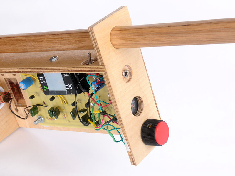
Drill one hole in the box to hold a 1/2″ PVC pipe fitting that will carry the reference coil, and another hole for the speaker.

Epoxy the PVC fitting into the box and let it set.

Put it all together

Tuck the reference coil inside the PVC and screw the brass nut onto the outer threads. Attach it (black wires) to the PCB.

TIP: If the nut or coil comes loose, try wrapping some Teflon tape (available from the plumbing section of the hardware store) around the threads.

Cut a 3′ length of 3/4″ hardwood dowel for the handle. Drill a 1/4″ hole through one end and connect the detector coil with a 1/4″ dowel peg. Thread the two large holes in the electronics enclosure over the handle.

Loosely wrap some some speaker wire around the handle and connect it between the detector coil and the PCB (yellow wires).

I hooked up the 8Ω speaker to the green output wires and a 9V battery to the power wires. Be careful of the polarity: red is (+) and black is (-).

I also wired in a switch on the red wire, which makes it much easier to turn on and off!

And last, but by no means least, you need to adjust the brass nut on the reference coil to create the right kind of tone. Here’s a video that explains this.

Improvements - volume control and headphone jack

To improve the “human factors” of your metal detector, add a volume control. The screeching and squealing that this device can make can be “upsetting” for anyone that might be around you.

Even better, add a headphone jack! Then you can use your treasure finder anywhere without disturbing others. I had to drill a couple more holes into the case to fit these.

I’ve included a schematic for the additional parts, which you add onto the two speaker connections. If you wire up the jack correctly it will mute the speaker when you plug the headphones in.

Conclusion

This project uses a phenomenon called "heterodyning" to combine two high-frequency signals to generate a much lower-frequency audio signal. Radio communication, precision rangefinders, and the Theremin all use this principle. You can learn more about heterodyning here.

Note: The idea of putting a small coil inside of a PVC pipe and tuning it by turning a brass nut is brilliant - I will definitely be using this in future projects.