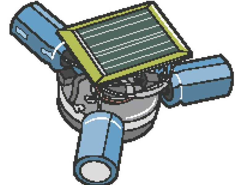
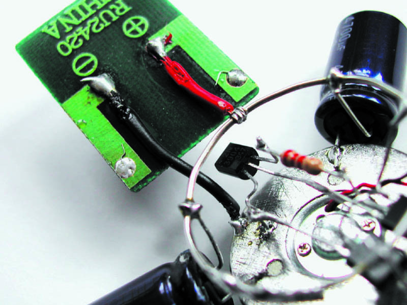
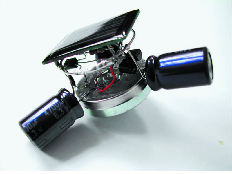
A Symet is a simple BEAM spinner that incorporates a common BEAM solar power management circuit called a voltage-tiggered (Type 1) Solar Engine. A “Trimet” is a Symet with three symmetrically-balanced components. A Trimet is basically comprised of the MSE, a DC motor scavenged from a cassette player, a solar cell, and three capacitors that store the energy from the cell (and also act as the main structure of the “bot”).
Projects from Make: Magazine
Trimet, Solar BEAM Top
A little spinning top that looks like a satellite in orbit.
- Like
- Digg
- Del
- Tumblr
- VKontakte
- Flattr
- Buffer
- Love This
- Odnoklassniki
- Meneame
- Blogger
- Amazon
- Yahoo Mail
- Gmail
- AOL
- Newsvine
- HackerNews
- Evernote
- MySpace
- Mail.ru
- Viadeo
- Line
- Comments
- Yummly
- SMS
- Viber
- Telegram
- Subscribe
- Skype
- Facebook Messenger
- Kakao
- LiveJournal
- Yammer
- Edgar
- Fintel
- Mix
- Instapaper
- Copy Link
Steps
Advertisement
Step #1: Building the voltage-triggered Solar Engine control circuit
- We’ll be freeforming this circuit, which means connecting components together directly, without a board. Normally I'd breadboard and test my circuits before soldering, but this one is so simple and has so few parts that we can live dangerously. Parts are easily desoldered and resoldered if there’s a problem.
- Face the two transistors up with their pins toward each other. Solder the base pin (middle) of the 3904 transistor to the collector pin of the 3906 (the right pin, as you read the printing).
- Use needlenose pliers to gently bend the 3904 emitter pin (left) 90 degrees to the side and its collector (right) 90 degrees up. Bend the 3906 base pin (middle) 90 degrees up and its emitter (left) 90 degrees to the side. Solder the 2.2k resistor from the 3904 collector to the 3906 base.
- Trim excess lead length from previous step. Place the 1381 voltage trigger to the right of the 3906, facing the same way. Solder its Pin 3 (right) to the 3904 emitter and its Pin 1 (left) to the 3906 collector. Finally, arc its Pin 2 (middle) around and solder it to the 3906 emitter (left). There’s your basic circuit, ready for motor and power!
Conclusion
Once you have the basic idea down, you can go crazy, improvising BEAMbots with greater storage capacity, better obstacle-avoidance strategies, or swankier, more attention-getting designs.
This project first appeared in MAKE Volume 06, page 76.