The original LED lanterns were featured in MAKE: Magazine, issue 30. When I first saw the article, I thought that they could only be used once, as they would have to be glued shut. When I read it, I realized that they were sealed with tape, and could therefore be opened, but not before I came up with a new idea.

What will the next generation of Make: look like? We’re inviting you to shape the future by investing in Make:. By becoming an investor, you help decide what’s next. The future of Make: is in your hands. Learn More.

Project Steps

The first step is to build the charger.

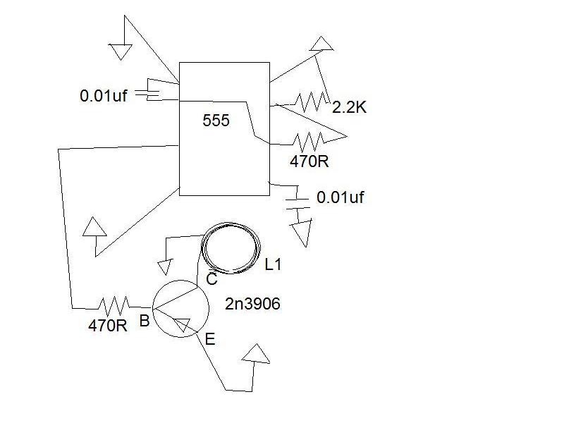
This is a basic 555 oscillator, with a frequency of about 160KHz.

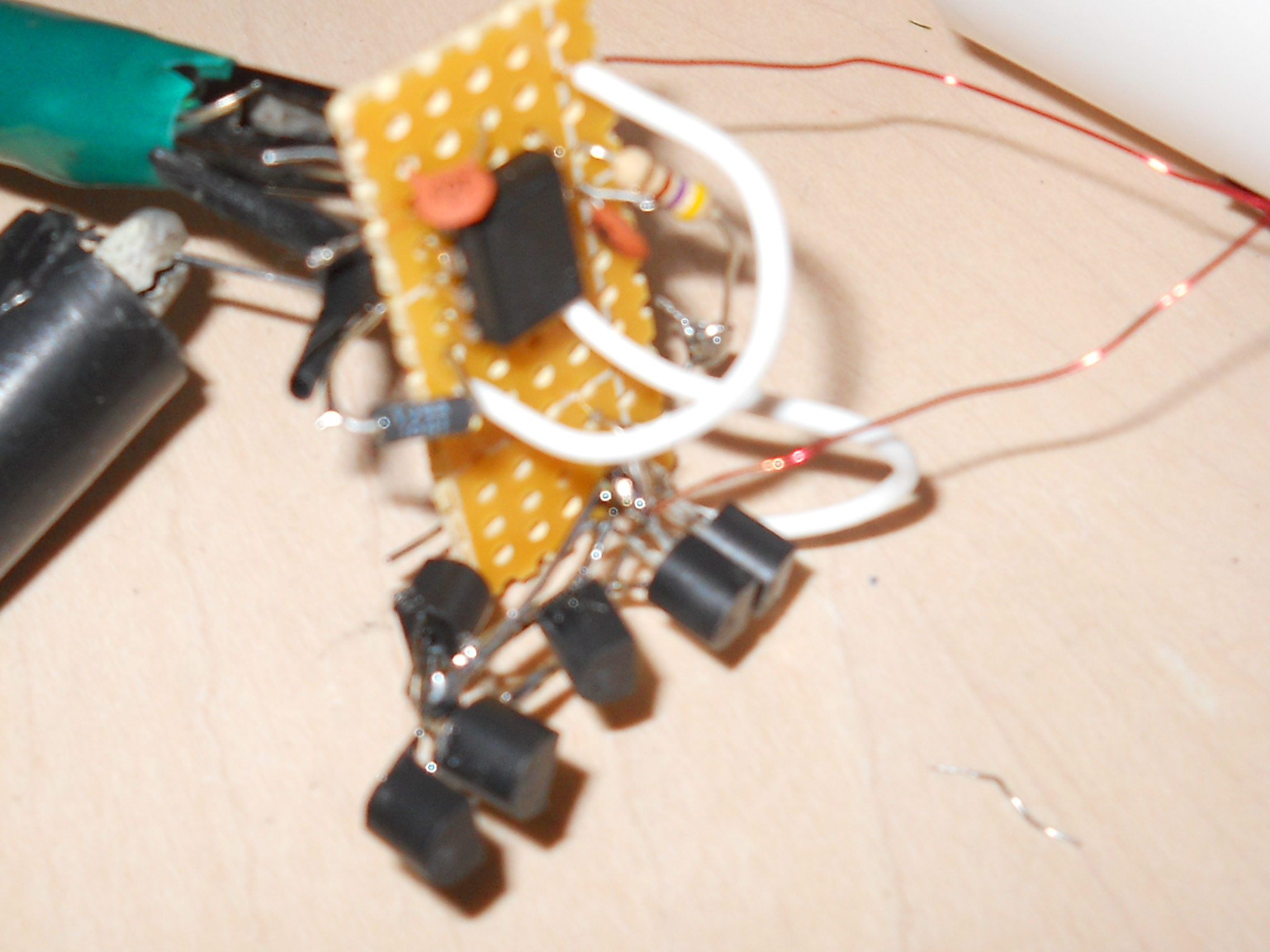
You MUST hook up several 3906s in parallel, or it will fry quickly. Apply 12V, and 10 transistors, then remove one transistor at a time until the remaining ones are too hot to touch. Replace ALL transistors with new ones, plus the removed one. It should run continuously without overheating.

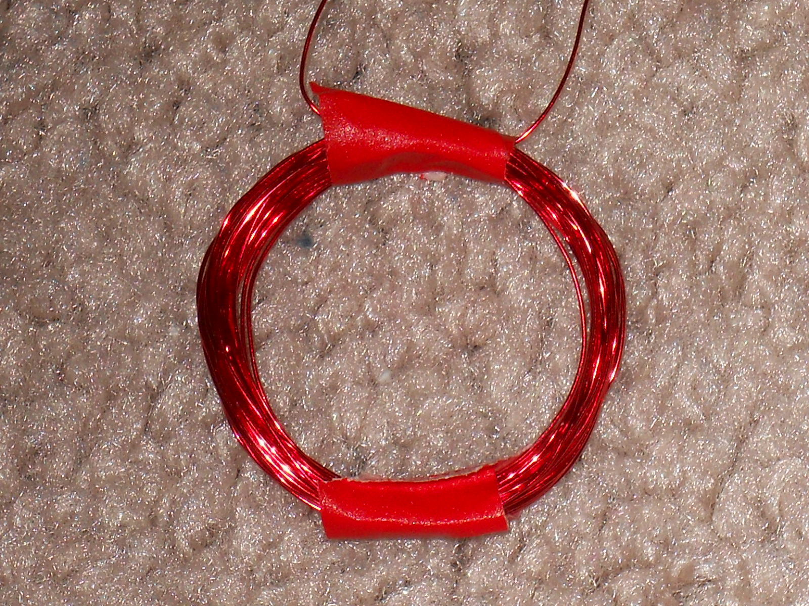
L1 is a wire coil of about 20-25 turns of magnet wire. It should have a diameter about that of the inside of the PVC cap.

This should be powered by large, rechargable batteries or a power supply at about 9V. A 9V battery will run out of power quickly, and will not deliver enough current.

If you have a CMOS 555, you should be able to increase the frequency by replacing the 2.2K resistor with a 470ohm resistor, and the 0.01uf cap with a 0.0047 cap. This should increase the inductive reactance of the coil, and allow you to use fewer transistors.

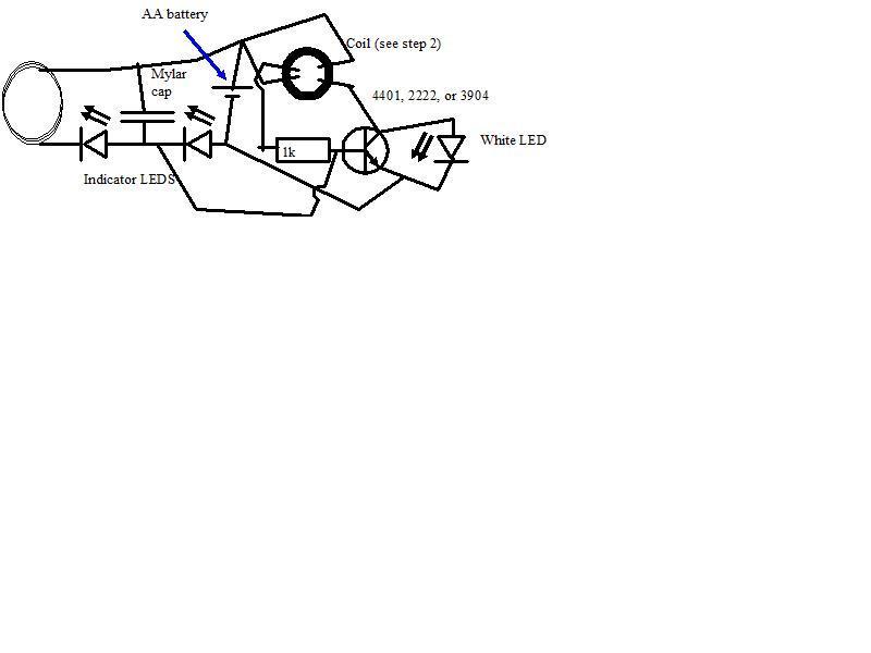
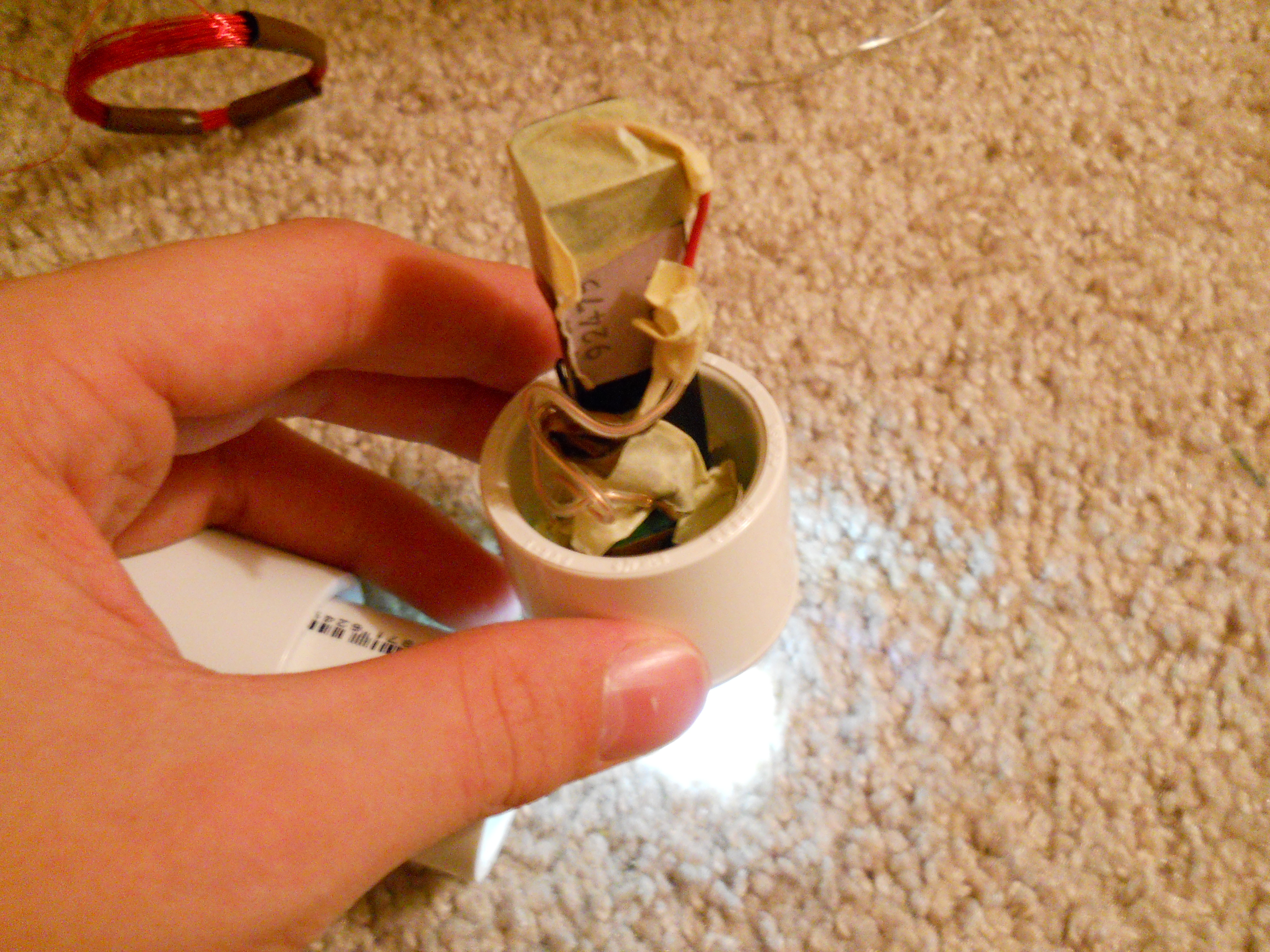
Now, we build the LED driver and battry charger circuit. Note that this will have to fit inside a 3″ piece of 1″ diameter PVC. The coil also must fit in a 1″ endcap. It should be 20-25 turns air core (2nd picture).

If this looks familiar, it is because it is a joule thief with a wireless power receiver. The coil labeled “coil (see step 2)” is made by wrapping 2 wires around a doughnut-shaped ferrite core six or seven times. The top two and bottom two wires are the same, so you connect one end of one wire to the other end of the other wire.

If you turn on the sender from step 1 and place the receiver coil flat on top of the sender coil, the indicator LEDs should light up. Charge the battery in its normal charger. When put into the circuit, the white LED should light. When the receiver coil is put near the sender, the indicators should light, and the white LED should turn off. If the white LED stays lit, flip the receiver coil. Make sure to mark which side works, as this is very important.

If the white LED does not light, check your wiring. If rechecking does not work, watch Bre Pettis’s video on the joule thief, as he does a better job explaining the joule thief part of the circuit.

If everything works, completely drain your battery by using a resistor. DO NOT CONNECT THE ENDS DIRECTLY. you must use at least a 15 ohm resistor. Once it is drained, put it into the receiver circuit. None of the LEDs should light.

Now, place the receiver coil on the sender coil as in step 2.

The indicators should light up, and after about 15 minutes, removing the power to the sender or moving the coils apart should turn off the indicators, and turn on the white LED.

If it does, then everything is working. If not, check wiring, coil polarity, the sender, and the battery.

Now, drill a hole in one PVC cap the size of your LED.

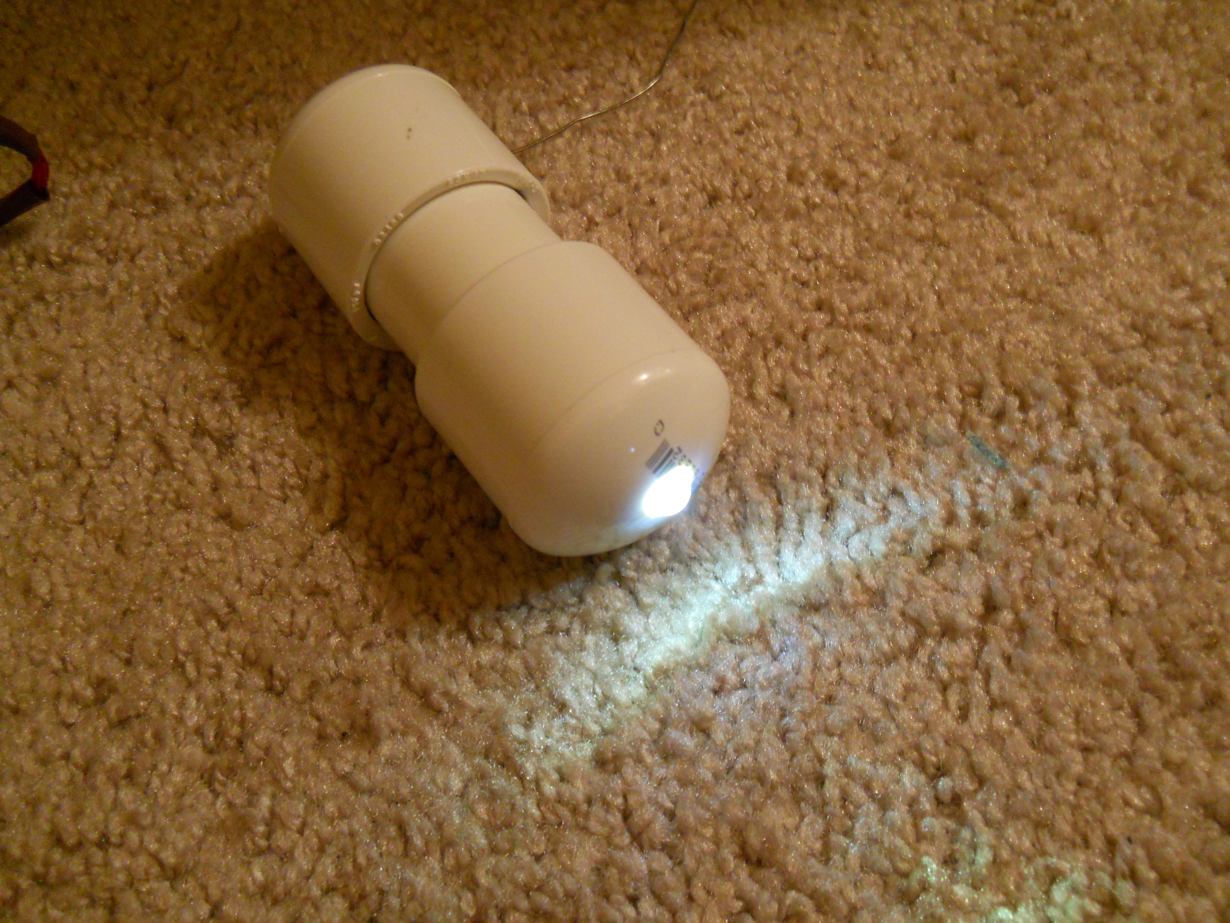
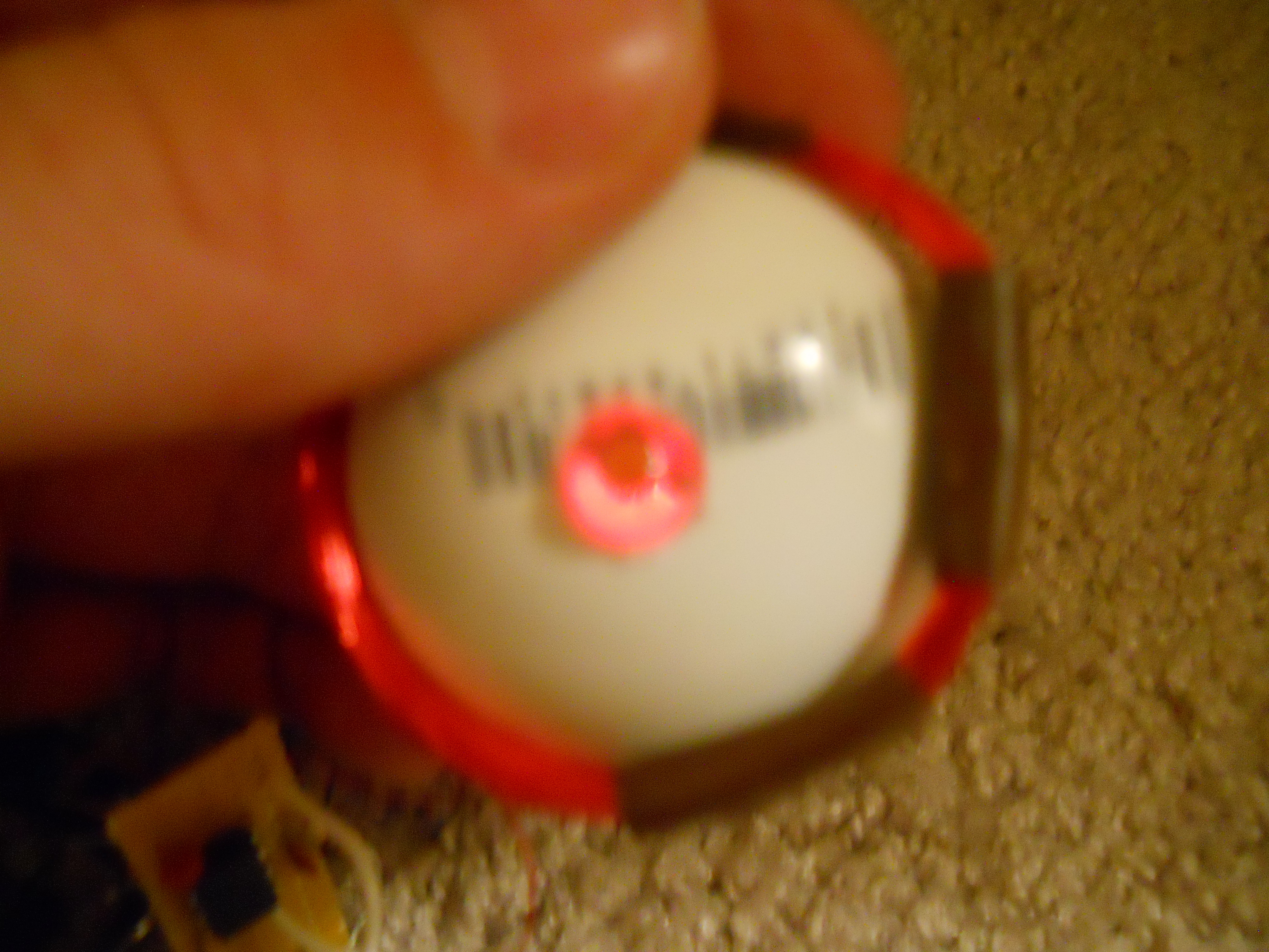
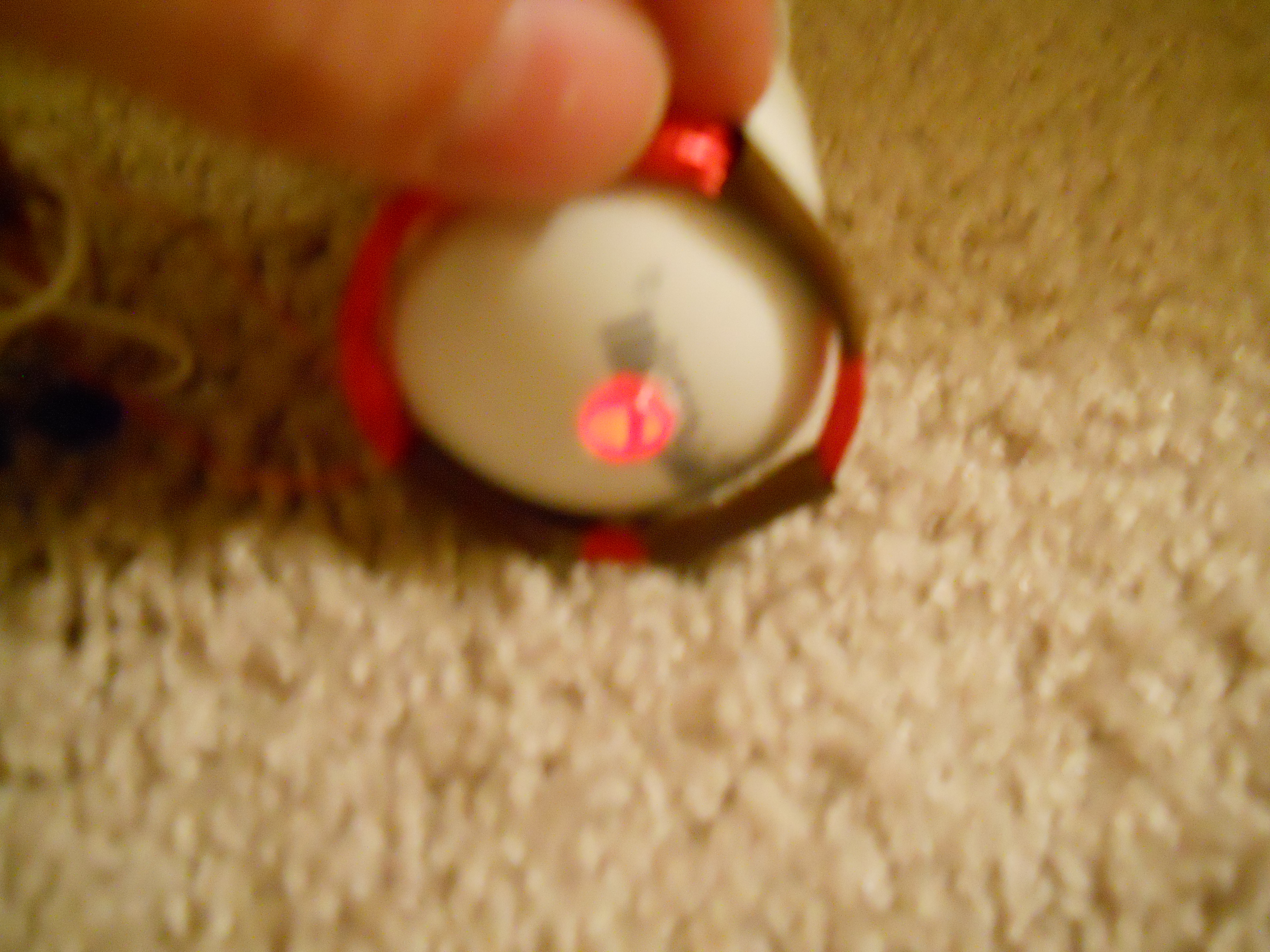
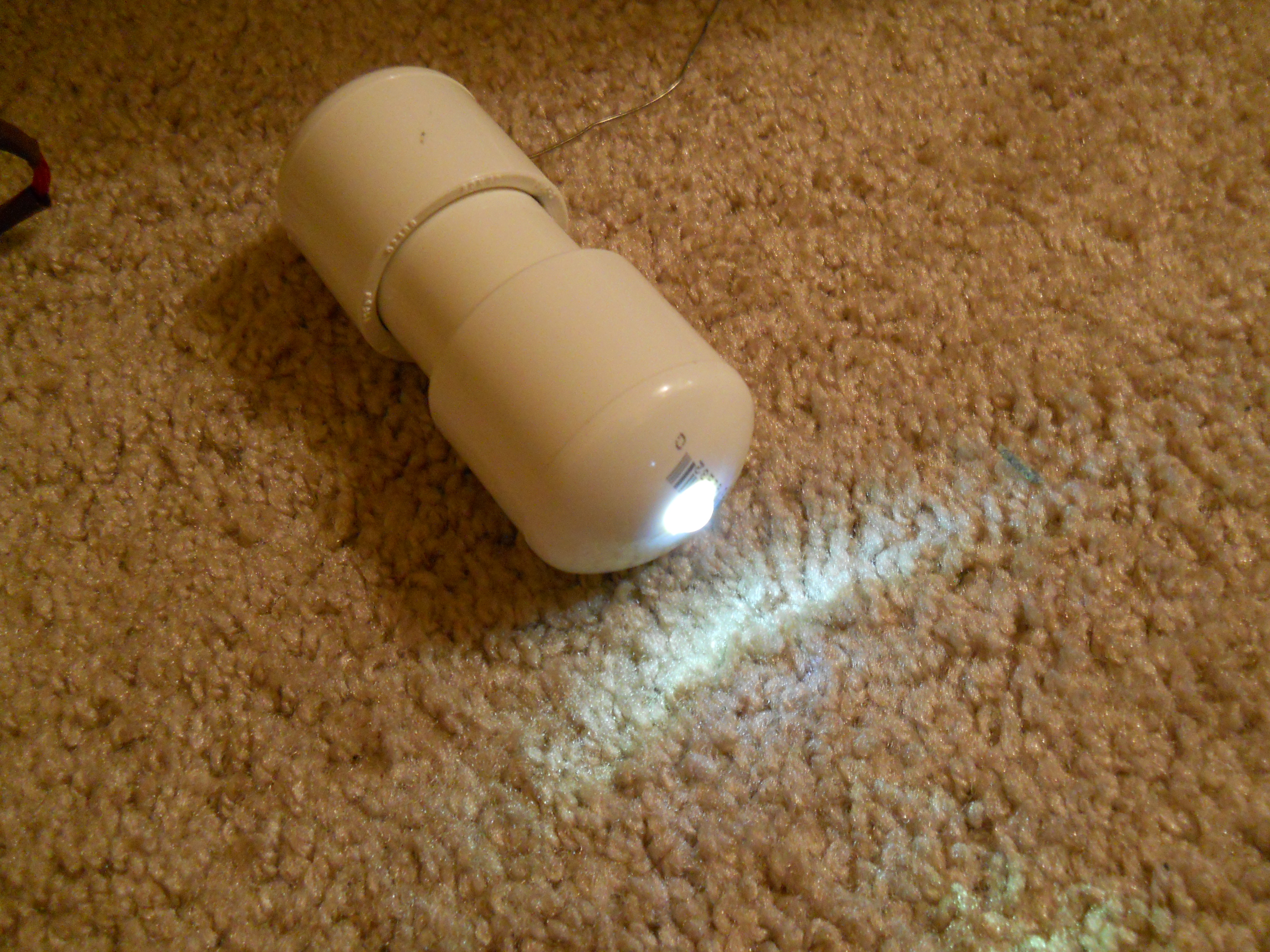
Put a bead of waterproof glue around the base of the LED, and insert it into the hole, with the rest of the circuit attached. Fit the indicator LEDs just behind the white LED, so that when they are on, you can see the light through the white LED, as in the picture.

Slide the 3″ piece of 1″ PVC over the circuit and the battery into the cap.

Test-fit the coil at the bottom of the undrilled cap, and slide it onto the PVC tube.

Test it with the sender circuit, placing the sender coil just outside the PVC cap.

As before, the white LED should turn off, and the indicator LEDs should turn on. if you did it correctly, the light from them should be visible through the top of the white LED (as in photo).

If everything works, then hot-glue the coil in place, and tape, glue, or epoxy the circuit and battery in place.

Then, pull the cap with the LED off, turn it 1/4 turn in one direction, and apply PVC glue to the pipe where the cap will slip on. The circuit will probably get in the way of the cap, so only glue the tube.

Then slide the cap on, and turn it 1/4 back to its original position. Test the circuit one last time. If you want it to be almost totally indestructable, then fill the pipe with epoxy before adding the second cap. If you are doing this, glue the cap with the LED first, as the cap with the coil does not protrude as far into the pipe.

Finish by gluing the second cap onto the pipe in the same way as the first.

Test it once again

You’re done!