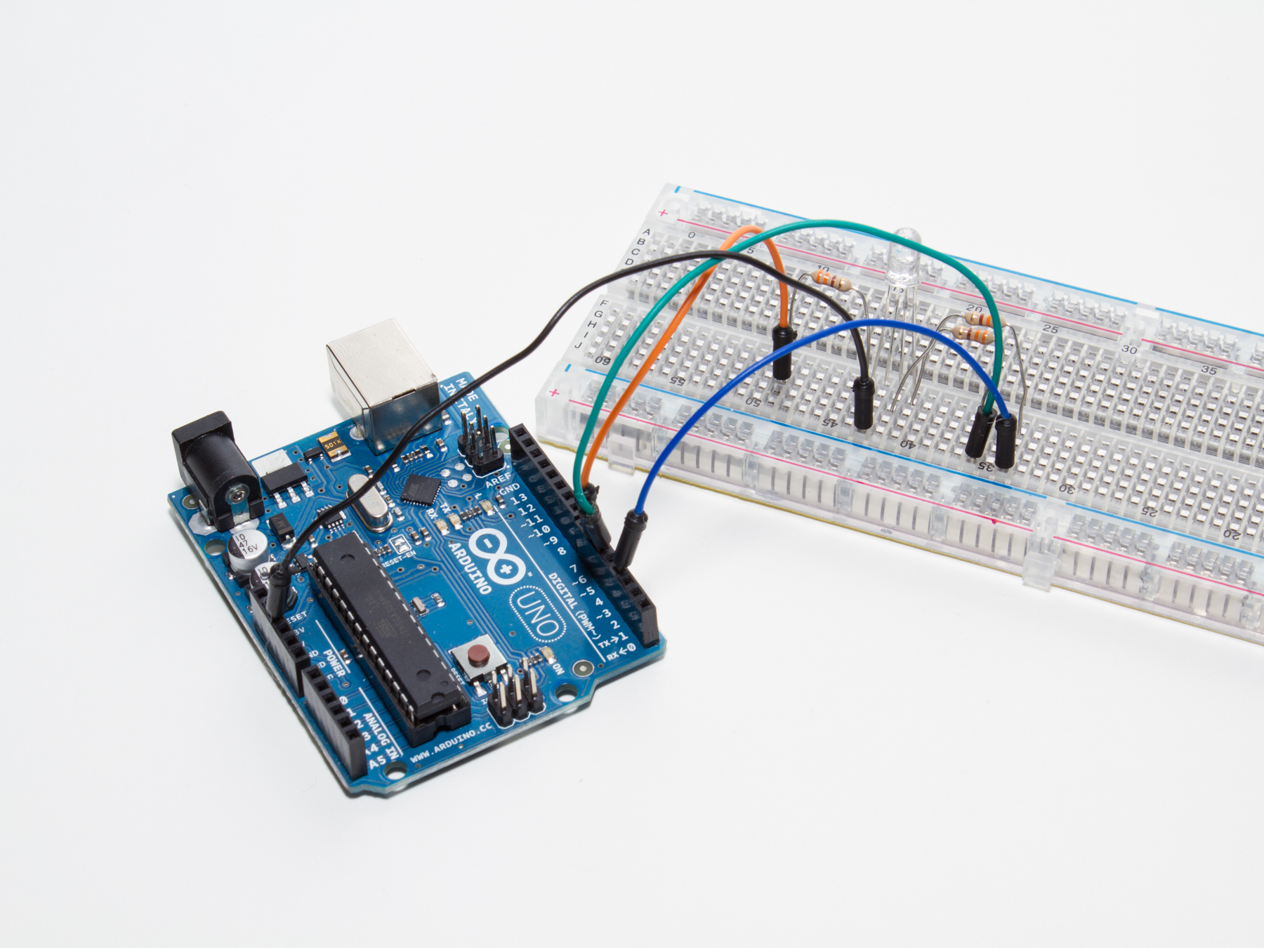
How to fade between colors with the Common Anode RGB LED, included in Maker Shed’s Ultimate Arduino Microcontroller Pack.
Projects from Make: Magazine
Use a Common Anode RGB LED
This is a quick tutorial on how to fade between colors with an Arduino and Common Anode RGB LED.

Plug in the RGB LED
Grab all the parts, and begin by plugging the Common Anode RGB LED into your breadboard.
Orient it in the breadboard with the red leg on the left, and power leg second from the left.
That’s power (long) leg to F42 on the breadboard, with the red leg right next to it in F43.
Begin the wiring
Now wire up the positive (longest) lead of the LED to the 5V header on the Arduino.
You can use a jumper from J42 to the Arduino.
Connect the three resistors, one from each of the three other LED pins to another spot on the transparent breadboard.
Place one 330 Ω resistor in G43 and G49.
Place another 330 Ω resistor in H41 and H35.
Place the last 330 Ω resistor in G40 and G34.
Connect the RGB pins to the Arduino
Next, connect the three pins of the LED to the Arduino.
Red goes to PWM Pin 6, from breadboard pin J49.
Green goes to PWM Pin 5, from breadboard pin J35.
Blue goes to PWM Pin 3, from breadboard pin J34.
Now you can grab the code from GitHub and upload it to your Arduino. Have fun!


