You’ve probably stumbled across amazing old vinyl LPs at a friend’s house, yard sale, or record store, but reluctantly passed them up, because in our mobile digital wireless world, a vinyl record is about as convenient as a telephone attached to the wall. Next time don’t pass them up, snap them up. With the Vinyl Digitizer Phono Preamp, you can “dub” records onto your computer and convert the sound files for your phone, MP3 player, car, or anywhere else you need music.

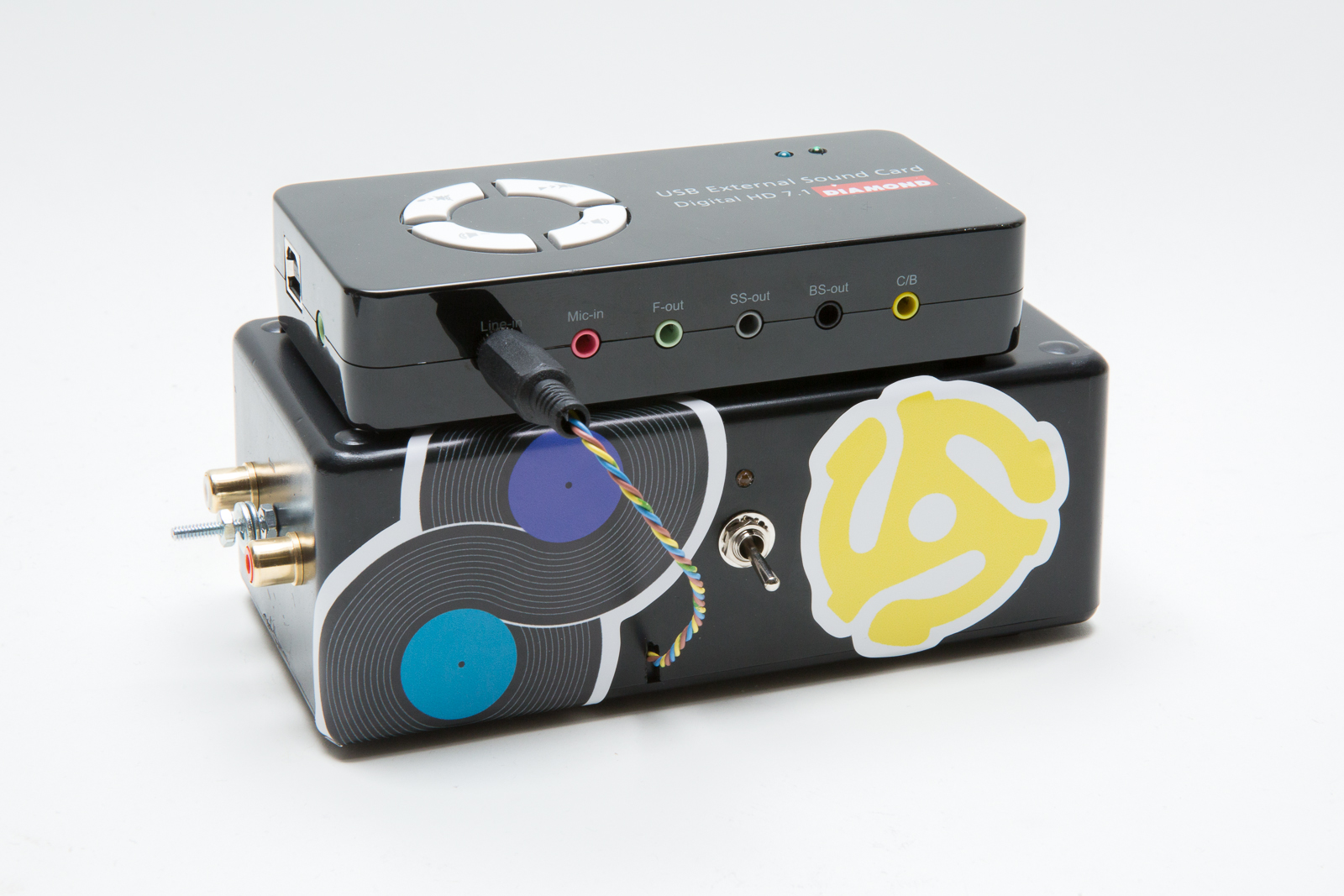
The system consists of 5 parts: your record turntable, the Vinyl Digitizer Phono Preamp that we’ll show you how to build, the Diamond Audio USB interface, your computer, and Audacity software. I designed the preamp to do three things: amplify the tiny signal from the turntable’s phono cartridge, apply a frequency equalization specifically for a vinyl record called the RIAA playback curve, and optimize the gain (volume amplification) to be compatible with the Diamond USB sound card. From there, the sound card converts the input signal to a digital data stream, and the Audacity software nimbly turns those old 45s, 78s, and LPs into new MP3s (or the digital audio format of your choice).

Vinyl Digitizer

Why should you care about a dead medium like records anyway? Because as an inquisitive person you’re susceptible to having your mind blown by what’s on them. Fifty-plus years of Gilbert and Sullivan, opera, rockabilly, Delta blues, prog rock, Lenny Bruce, Beethoven, Balinese gamelan, jug bands, “Yardbird” Parker, klezmer, and much more that you can’t even imagine. Long playing records were the primary format for music distribution for the second half of the 20th century, a tremendous time for musical creativity and performance. They were produced by the hundreds of millions. From Bozo Under the Sea to Van Cliburn at the Tchaikovsky Competition, it’s all still out there and much of this material never made the transition to digital.

Here’s how to build the Vinyl Digitizer Phono Preamp and bring your discoveries into the future with you.

Project Steps

Prepare the circuit board.

You’ll assemble the preamp circuit on a RadioShack printed circuit board. But first, label the PCB hole positions to help you place the components.

Use a fine-tipped marker to number the traces on the copper side of the board (the bottom), as shown, before installing components.

Flip the board over to the component side (the top) and number the traces to match.

Label the 5 holes of each trace with letters A through E, with A at the center of the board and E at the outside. Thus the inner hole on the trace at the upper left is 1A and the outer hole of the trace at the upper right is 20E.

Hole 16E will have 2 wires in it. Widen the hole with a small file or drill to approximately 1.5 times its width. Be careful not to remove all of the copper from the hole on the solder side.

Mark and drill the enclosure.

Cover one long face of the box and the short side to the left of it with masking tape. Also tape the inside surface of the bottom cover of the box.

NOTE: The 3mm hole on the front of the box is for a power indicator LED. You may wish to skip this component. The LED draws 5mA of current from the battery. The audio circuit itself draws 3.7mA , so using a power indicator LED will shorten battery life by at least 50%. If you decide to skip the power LED and save battery life don’t drill this hole, and skip all following instructions for the LED. The switch position itself will indicate if the unit is turned on (up).

Measure and mark the positions for the drill holes in the box, following the photos here.

The bottom of the box will hold the circuit board. Place the circuit board against the right edge as shown, centered vertically, and mark the upper left and lower right hole positions.

Drill all the holes. You can use a 1/8″ drill bit for the 3mm holes.

Make the LED power indicator (optional).

Skip this step if you’re eliminating the power LED to save battery life.

Cut a 2″ length of red 24ga wire and a 2″ length of black 24ga.

Locate the cathode lead of the LED. It should be shorter than the anode lead, and it’s typically indicated by a flat spot on the rim of the LED body.

Clip the cathode lead down to 5mm, shorten one lead of the 3,300Ω resistor, and solder the resistor to the cathode.

Clip the free resistor lead to 5mm and solder the black wire to it.

Clip the LED anode lead to 20mm and solder the red wire to it.

Cover the resistor and all bare wire with 2 lengths of 4mm heat-shrink tubing, and shrink it to insulate the connections.

Place the LED through the 3mm hole on the front of the box and glue it in place with the hot glue gun.

Install the RCA input jacks.

Each RCA input jack comes with a grounding washer. Bend the tab of each grounding washer at a 30° angle to the ring.

Strip a 3″ length of 24ga solid core wire.

Solder one end of the bare wire to each of the ground washer tabs.

Wrap the center of the wire around the #4 × 1″ screw and tighten a nut to hold the wire against the head.

Pass the screw through the 3mm hole on the end of the box from the inside. Nut it tightly on the outside. Place two #4 washers on the screw and another nut, loosely.

If the RCA jacks are color coded, place the red one on the right and black on the left, as viewed upright from the outside. (The third photo here shows it upside down.) Pass the RCA jacks through the jack holes from the outside. Place one ground ring on each jack inside the box and nut both jacks tightly.

Build the PCB, stage 1.

NOTE: 1/8 watt resistors are specified for this project due to their small size; 1/4 watt resistors will function the same but may have to be placed vertically rather than horizontally due to their greater length. Also, film capacitors vary in size and shape; there’s no harm in bending the wires to reach the PCB holes, but look carefully at all the PCB photos to make sure you’re not obscuring component holes or screw holes when you place your capacitors.

When placing a component, solder it in place and clip off the lead unless instructed otherwise. Some holes get multiple wires. This is tweezer work. A pair of eyebrow tweezers is ideal for fine wires. A fingernail clipper makes a great wire cutter.

Install the 8-pin DIP socket U1 in holes 4A–7A, 14A–17A.

Install 0.10µF film capacitor C6 in holes 17D–20C.

Install 0.10µF film capacitor C5 in holes 7C–9C. bend the leads as needed to reach.

Install 47K resistor R105 and 330pF capacitor C104 in holes 6D–9D so that they’re in parallel.

Install 1K resistor R103 in holes 9B–5B.

Install 82K resistor R101 in holes 4D–5D.

Build the PCB, stage 2.

Install 5,100Ω resistor R102 and 0.033µF capacitor C102 in holes 2C–5C in parallel.

Install 18K resistor R104 in holes 9E–8D.

Install 0.47µF capacitor C103 in holes 4E–8E.

Build the PCB, stage 3.

Install 0.033µF capacitor C101 in holes 4B–2B.

Install 47K resistor R205 and 330pF capacitor C204 in holes 9A–14B in parallel.

Install 1K resistor R203 in holes 20A–15B.

Install 82K resistor R201 in holes 15D–16D.

Install 5,100Ω resistor R202 and 0.033µF capacitor C202 in holes 15C–18C in parallel.

Install 18K resistor R204 into holes 19B–20B.

Prepare an 8″ length of red 24ga wire and install it in 17E.

Install 0.033µF capacitor C102 in 16E–18D. Solder 18D only, not 16E.

Install 0.47µF capacitor C203 in holes 19E–16E. Solder both. IMPORTANT: Leave 4mm between the capacitor wire and the PCB as clearance for the mounting nut. (See how the lead of C203 passes over the mounting hole at the upper right? Yeah, don’t do that. A screw has to go there, and moving the capacitor later to make room for the nut was a hassle.)

Build the PCB, stage 4.

Solder an 8″ black 24ga wire to 7E.

Solder an 8″ orange wire to 6C. This is the left channel input.

Solder an 8″ green wire to 14C. This is the right channel input.

Solder an 8″ grey wire to 1A. This is the input ground.

Solder an 8″ yellow wire to 8A. This is the left channel output.

Solder an 8″ blue wire to 19D. This is the right channel output.

Solder an 8″ brown wire to 1E. This is the output ground.

On the back (copper) side of the board, solder an insulated jumper from 20A to 9A using the solder already on the board.

On the front (component) side of the board, solder a jumper from 1D to 20D.

Two battery clips are used. Solder the black wire from one battery clip to 20E.

Solder the red wire of the other battery clip to 1C.

Gather the orange, green, and gray wires and twist them together, pointing in the direction indicated in the photo.

Gather the blue, yellow, and brown wires and twist them together, pointing in the direction indicated in the photo.

Gather the red and black 24ga wires from 7E and 17E (not the battery clip wires) and twist them together, pointing in the direction indicated in the photo.

Using a magnifier, carefully inspect the solder side of the PCB. Look for cold solder joints, for wires not wetted by solder, and especially for solder splash bridges between traces. If you see a solder bridge, scrape it away with the point of a knife. No matter how careful I am, I always have one or more goofs on these small PCBs.

Solder the output wires to the plug.

Remove the plastic housing from the 1/8″ phono plug and slide it down the yellow/blue/brown wire bundle.

Using a multimeter, determine which solder tabs on the plug connect to the tip of the plug (left signal), the ring of the plug (right signal) and the body of the plug (signal ground).

Solder the yellow wire (left output) to the solder tab for the tip.

Solder the blue wire (right output) to the solder tab for the ring.

Solder the brown wire (output ground) to the solder tab for the body.

Gently crimp the ground bar’s tabs around the wire bundle, making sure not to cut the insulation and cause a short.

Use a multimeter to check for short circuits between ground/ring and ground/tip. The correct resistance reading is 47,000 ohms (47kΩ).

Install the plastic housing on the plug.

Connect the input wires to the RCA jacks.

Solder the green wire of the green/gray/orange bundle to the right (red) jack signal tab.

Solder the orange wire to the left (black) jack signal tab.

Solder the gray wire to the bare wire loop between the ground lugs.

Bend the bare wire loops against the wall of the box so they won’t cause shorts.

Install the power switch.

The power switch has 3 pairs of solder tabs, but we’ll use only 2 of pairs, which I’ve numbered 1 through 4, including the central pair (3,4). Solder the twisted red and black pair of power wires from the PCB to switch terminals 3 and 4 respectively. When stripping these 2 wires, leave 3mm of bare wire exposed when they’re soldered on.

Solder the red wire from a battery clip to terminal 1 on the power switch as shown. Solder the black battery clip wire to terminal 2.

Install the power switch inside the project box, so that its 2 unused solder tabs are nearest the top of the box, and terminals 1 and 2 (battery clip wires) are nearest the open bottom of the box. Tighten the switch’s nut on the outside.

Solder the red wire from the LED to the red PCB power wire (twisted) at terminal 3.

Solder the black wire from the LED to the black PCB power wire at terminal 4. In this way the LED is powered when power is connected through the switch from the battery wires to the PCB.

Final assembly.

Insert the TL082CP IC chip into the socket. The notch in the chip body orients toward the end of the board with PCB rows 1 and 20. This places the ‘pin 1’ indicator dot on the chip body at PCB hole 4A. Take standard antistatic precautions with the chip, as its input JFETs could be damaged by a static discharge: leave it in its conductive foam until you’re ready to install it, then touch a metal object to discharge any static before handling the chip, and keep yourself grounded while handling it.

Install the two 9V battery holders on the box bottom with #4 × 3/16″ screws and nuts as shown. Pass the screw through from the outside so the nut is on the inside.

Using #4 × 1/4″ screws and nuts, attach the PCB to the bottom of the box in the orientation shown. Do not overtighten the screws or the PCB could be damaged.

Place a pair of fresh 9V batteries in the clips and slide them toward the near end of the box bottom. Orient the batteries so their terminals are nearest the PCB and positive terminal is closest to the bottom of the box.

You should use 2 new 9V batteries of the same type so that they discharge at the same time.

Turn the power switch off (down) and snap the battery connectors onto the battery terminals. Flip the power switch up and make sure the LED comes on.

Close up the box, carefully moving the wires around as needed for clearance. Pass the output wire/plug through the slot at the front of the box.

Install the 4 Phillips screws in the bottom of the box. I stuck 4 rubber feet on the bottom of mine to help it stay in place when hooked to cables.

Hook it up.

Set the Diamond Audio USB External Sound Card on top of your Vinyl Digitizer Phono Preamp and plug the preamp’s output plug into the sound card’s Line-In jack.

Using the supplied USB A/B cable, connect the Diamond sound card to the computer. It should appear as External USB Sound Card or similar name.

Plug the turntable’s left and right output plugs into the input jacks of the Vinyl Digitizer Phono Preamp. IMPORTANT: If your turntable has a ground lead, securely connect it between the washers on the screw between the input jacks. Without it, there will be buzzing noise along with the audio.

Start the Audacity software and select the external USB audio device as the input. The manual for the Audacity software is excellent, and can be downloaded separately.

Now digitize some vinyl!

Refer to the Audacity manual page “Sample Workflow for LP Digitization” for detailed instructions on how to record and save records. It’s easy. Here’s how I do it:

Turn the Vinyl Digitizer Phono Preamp on and start a record playing. Press the R key on your computer keyboard to begin recording. Press the space bar to stop recording.

You’ll have to adjust the recording level of the software to get adequate volume while avoiding signal clipping. With my turntable the correct recording level setting was between 0.20 and 0.30 depending on the record. If the continuous display of the recorded wave shows many vertical red lines, the signal is clipping — turn down the input level until most of the clipping disappears.

You should have no trouble making good digital copies of records with this system using the Audacity manual as a guide. I browsed the manual for 10 minutes, ignoring all of the finer details, and was making good copies of sides immediately.

How the Preamp Circuit Works

One channel of the preamp circuit is shown. Signal from the turntable enters at the left. Resistor R5, 47K, and capacitor C4 form a load for the phono cartridge.

Capacitors C6 and C5, 0.10µF, bypass the power supplies at high frequencies to provide low source impedance on the supply.

Capacitor C3, 0.47µF,and resistor R4, 18K, form a high-pass filter to block DC and low-frequency noise from the output.

Operational amplifier U1, the TL082CP chip, is a high-gain, differential-input dual amplifier chip.

R1, R2, R3, C1, and C2 form a nonlinear feedback network around the op-amp. They feed more treble than bass back to the amp’s negative input. This causes the amp’s gain to be lower at high frequencies than at low frequencies, providing the RIAA EQ contour required for record playback.

How the Vinyl Digitizer Phono Preamp System Works

The Vinyl Digitizer Phono Preamp is compatible with almost any phono cartridge. It was tested with a typical Audio Technica Moving Magnet cartridge having an output signal specification of about 4mV. Low-output Moving Coil phono cartridges require different amplification and electrical interfacing, but you’re unlikely to be using one of them with this system.

The Vinyl Digitizer Phono Preamp amplifies the tiny signal from the phono cartridge and applies a very specific frequency equalization called the RIAA playback curve. This EQ is necessary because it is complementary to an EQ curve applied to the recording when it was cut to the record. Why use an EQ curve when recording? Emphasizing the treble and deemphasizing the bass during recording accomplishes 2 things: The physical bass waves in the record groove are made narrower, allowing the grooves to be spaced closer together for longer playing time. And the increased treble on the record is pulled back down by EQ in playback, taking the surface noise in the record with it and resulting in a better signal to noise ratio.

Without the playback RIAA playback EQ the sound from the cartridge would have far too much high frequency and no audible bass. The Preamp applies the playback EQ curve by amplifying the lowest bass by about 45dB, amplifying the midrange at 1,000Hz by about 25dB and amplifying the highest treble by about 5dB. The Vinyl Digitizer Preamp’s gain (volume amplification) has been optimized to be compatible with the Diamond USB External Sound Card.

From the Vinyl Digitizer Phono Preamp, the amplified and equalized signal goes to the line input of the Diamond USB External Sound Card. The sound card converts the input signal to a digital data stream and transmits it to the computer via the USB connection.

On the computer, the Audacity software is used to record the digital music stream as a file. The file can easily be edited, and exported in a variety of formats for digital playback. Again, you can refer to Audacity’s excellent manual page “Sample Workflow for LP Digitization” for detailed instructions.

About Turntables

Turntables may seem like complex, mysterious devices but they have simple functions: turn the record at a constant speed and orient a pickup cartridge on the groove at the correct angles and pressure. Proper turntable setup is necessary to get good sound from a record but there’s no need to make a major obsessive engineering project out of it. Like I have for the last 40 years.

If you suspect your turntable might not be up to the task, take it to an audio shop for a checkup or consult hobbyists on a discussion site like AudioKarma. Anyone with reasonable dexterity, simple tools, and a little patience can set up a record player for great performance.

About Records

Records are a delicate physical medium and require a bit of care. Any used vinyl you come across will probably need a good wet cleaning to get good playback sound quality. I use a VPI HW-16 automated record cleaning machine because I’m lazy, but manual cleaning works fine.

Work on a clean surface like a glass tabletop or a countertop. Handle the record only by the edges, and avoid letting anything touch the grooves. Spray the groove surfaces with a cleaning solution, gently rub in the direction of the grooves with a soft paintbrush to loosen dirt, and remove the fluid by wiping concentrically with a clean micro fiber cloth.

The cleaning solution I use is half steam-distilled water and half 90% isopropyl alcohol, with a drop of Dawn dishwashing detergent per quart as a surfactant. You can mix a lifetime supply of this for about $3. Keep it in a sealed container or the alcohol will evaporate.

I wet-clean any record only once, then wipe the surface with a soft record cleaning brush like a Discwasher to remove dust before each play.

Standard paper record sleeves will shed dust particles on the record surface and cause noise. I replace them with polyethylene record sleeves that cost about $0.20 each in small quantities.

Dedication

To my dad, Dave Hershberger, whose records amazed me when I was a little kid. Thanks for a lifelong relationship with music. We need to burn those Sinatra sides so you can listen to them in the car.

To my wife, Gina, who I met at a concert. When I found out she had the Horseflies record Gravity Dance, I knew she was the one.