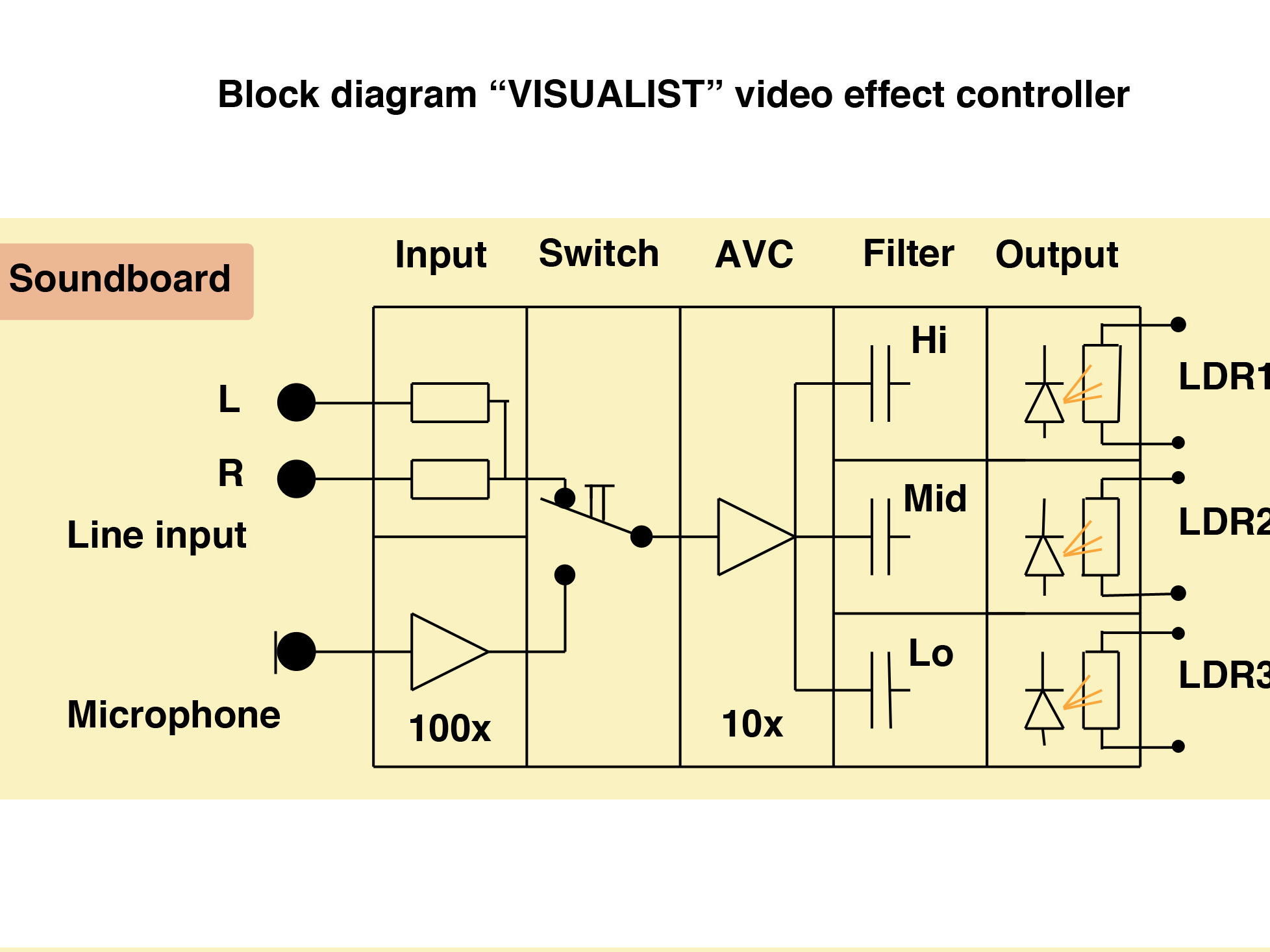
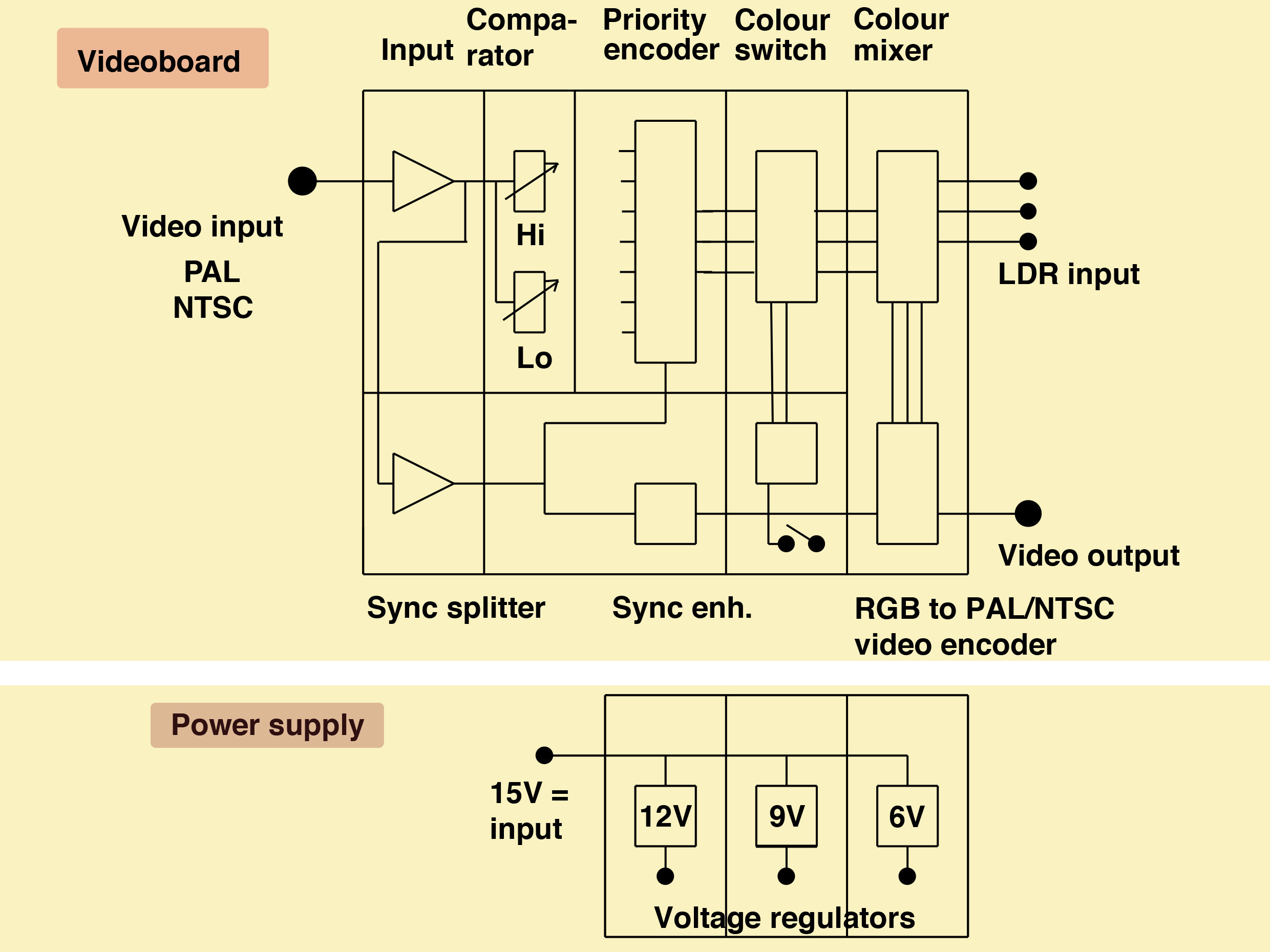
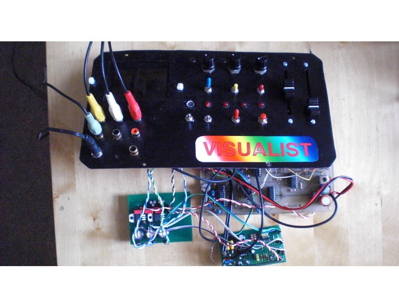
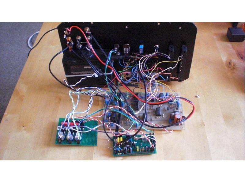
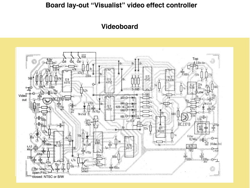
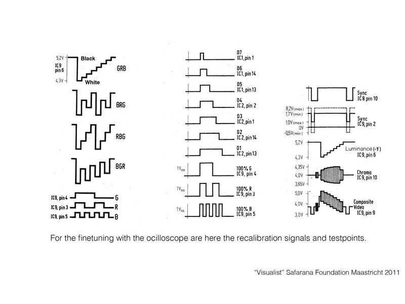
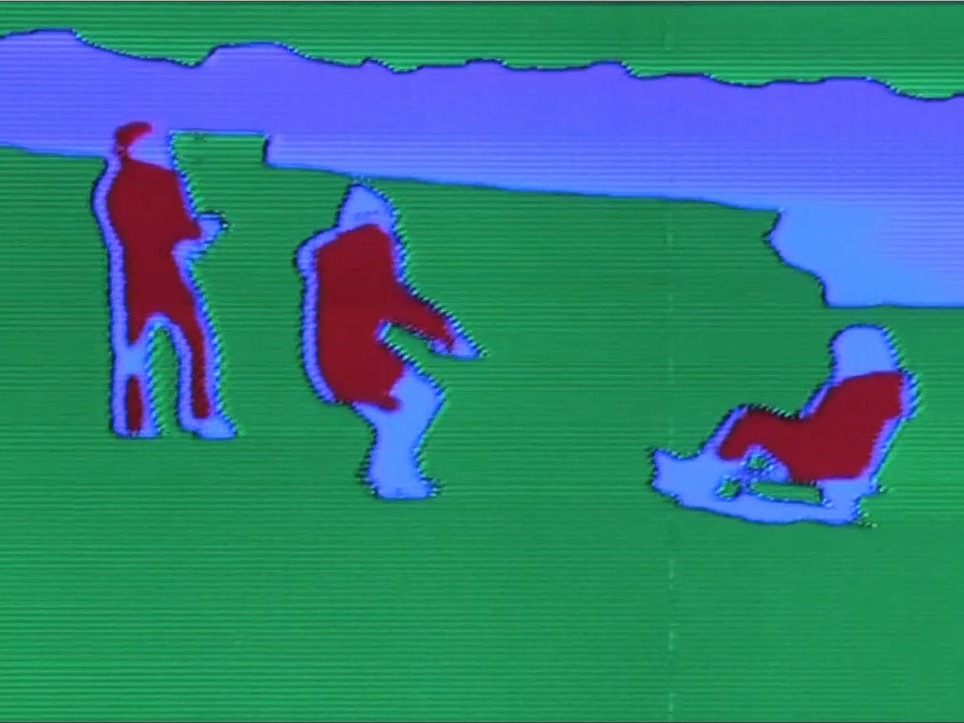
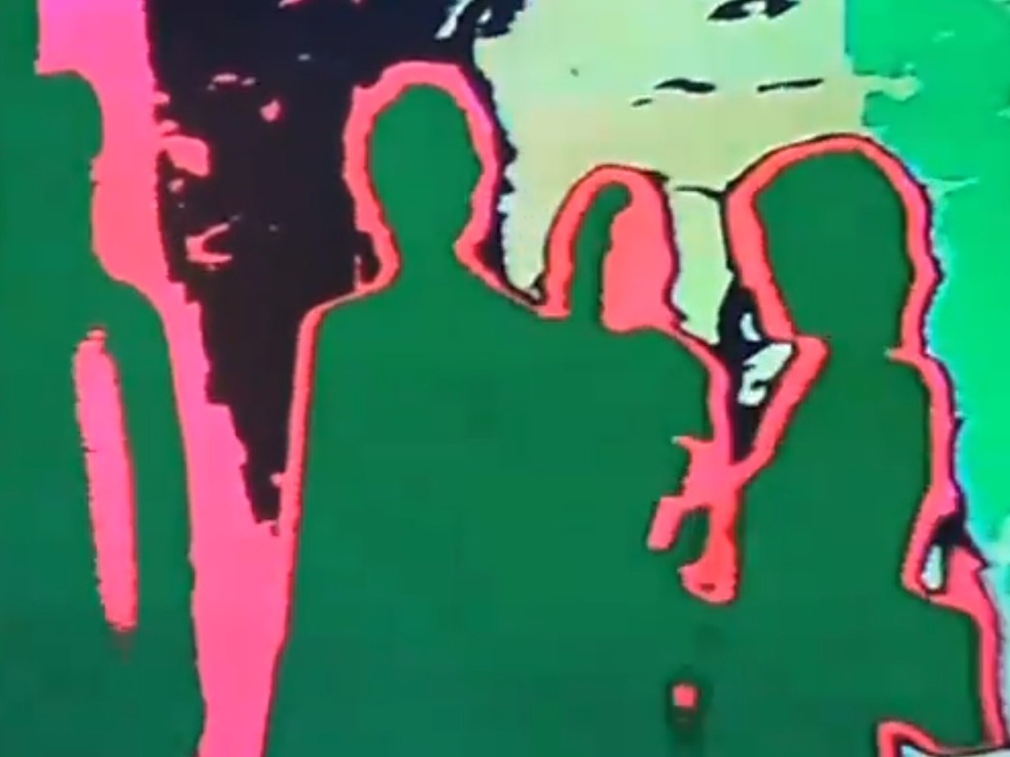
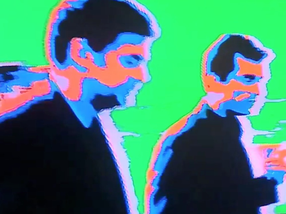
The first picture shows the block diagram of the video board; a kind of flow diagram.
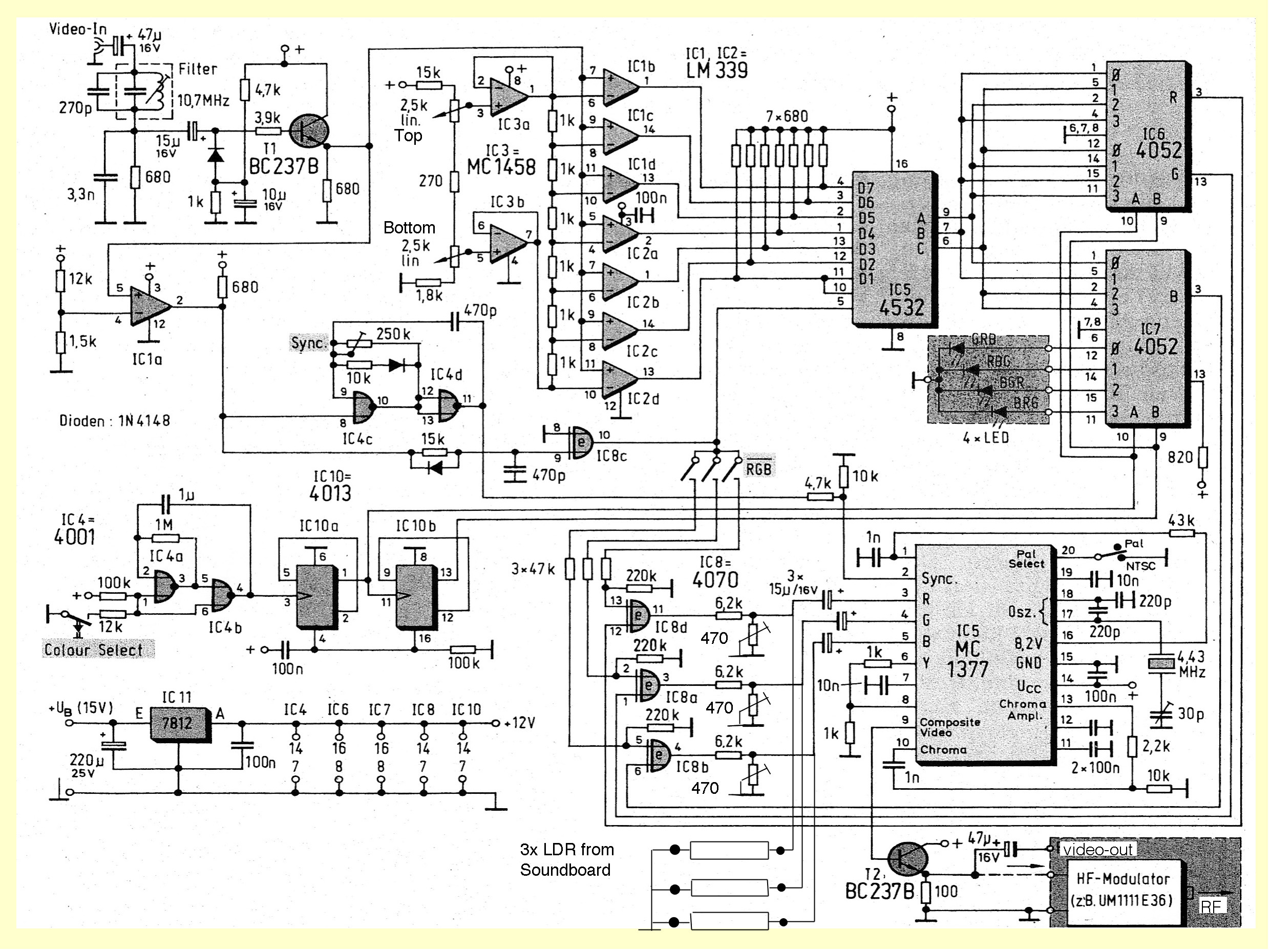
In this circuit the color video input signal is made into a b/w signal by cutting off the color burst using a notch filter (10.7Mhz). It’s not perfect but it’s sufficient.
The signal is split in 2 directions: 1- Via the comparator IC1a the sync pulse is passed to the oscillator IC4c/d (31250khz) to make a semi-normal PAL-sync-mix for IC9, the “famous” MC1377P RGB to PAL/NTSC encoder. 2- The way through the seven comparators IC1 and IC2.
With six resistors between IC3a/b we can control the upper and lower threshold and the threshold for every luminosity level in between. In other words, the signal will be “sliced” into 7 luminosity levels. Each level will produce a color out of a range of combinations chosen by IC6 and IC7. It’s in fact a “false” color generator.
After the comparator the signal passes through a priority encoder IC5 that results in a 3-bit-word. IC6 and IC7 (1 out of 4 analog switches) are doing the color change. The 2-bit control signal is made by IC10 and IC4a/b.
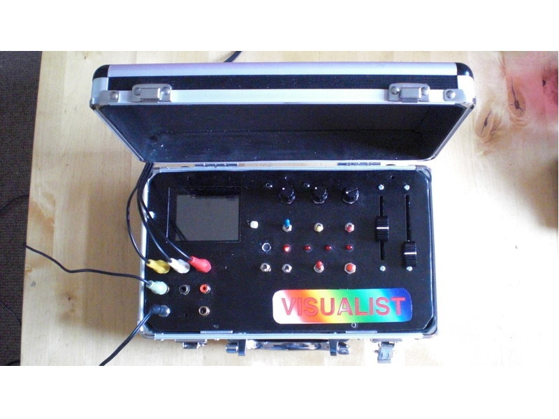
Pressing the “color select” button briefly makes a color change; holding the button down makes a continuous color change. More effects are produced by the RGB inverter switches; they invert the color layers.
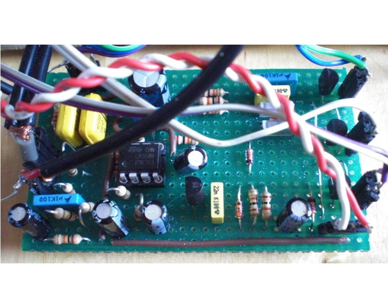
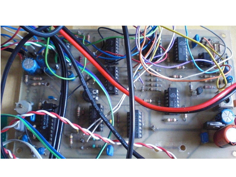
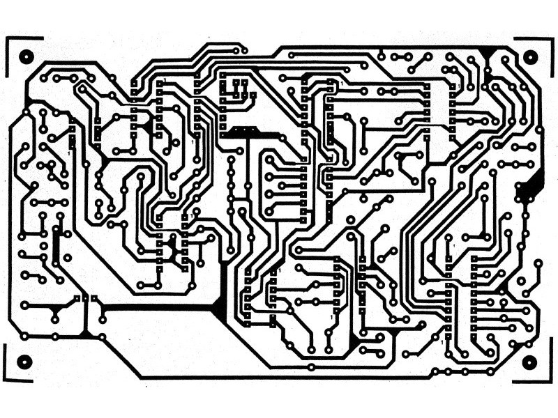
The third photo shows the components built on a printed circuit board.
