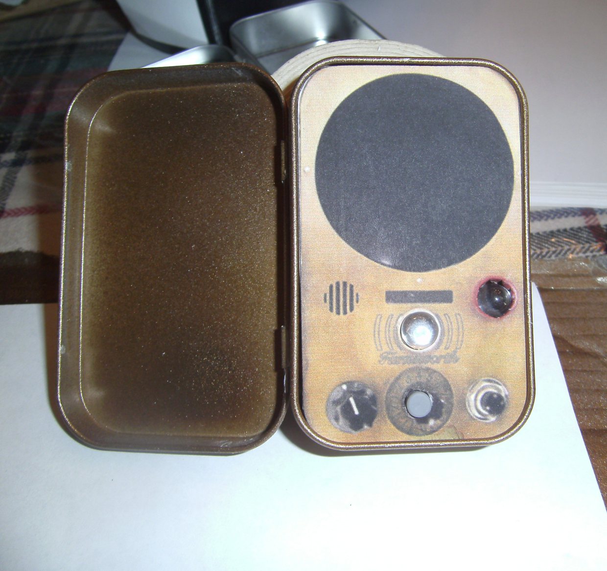
Presenting the Mini Farnsworth Photo: Andrew Terranova
Presenting the Mini Farnsworth
Photo: Andrew Terranova

If you are a fan of Warehouse 13, you are familiar with the Farnsworth device that the characters use to communicate. It is named after real-life inventor of the first fully electronic television, Philo Farnsworth. There are many examples of replicas for the Farnsworth by movie FX hobbyists that require machine shop tools or laser cutters to make. This is not one of those.

This is a miniature version of the Farnsworth. It is cheap, fairly easy to build, and will in no way pass for the actual device. However, if you are looking for an easy build with fun results, you may like to try it.

You can see it in action in the video below.

YouTube player

Want to give it a try? Just follow the steps and you’ll be calling up your favorite Warehouse agent in no time.


Project Steps

Paint the Tin

Painting is by far the most time-consuming part of this project. Follow the instructions on the spray paint cans, and be sure to work in a well-ventilated area.

I’m not an expert at painting faux finishes, so I’m not going to provide a lot of in-depth instruction. I think my paint job turned out OK, but maybe you can do even better!

Start by cleaning the tins, if they were used for mints. If you bought new tins from a craft store, you probably don’t need to clean them.

Using a small flat head screwdriver, carefully pry the hinges of the tin open just far enough to remove the lids for painting as shown in the first picture.

Apply a primer coat on all sides of the tin.

Apply a base coat of metallic gold paint, then accent with the darker brass paint.

After the paint is dry, apply a clear matte finish to protect it.

Consider a very light sanding with 220 grit paper as a final step. You should wind up with something that looks somewhat like aged brass.

Add the LED to the Recorder Module

The recorder module has an integrated surface mount LED that blinks during playback. We need to solder on the 10mm LED.

Connect the 9V battery to the recorder module. Record a sample by pressing and holding the button on the small circuit board that connects to the main board with two wires. Find the integrated LED, which should light red during recording.

Now identify the positive (anode) lead of the LED, which is usually longer. Carefully touch the leads of the 10mm LED across the contact points for the integrated surface-mount LED. The anode of the 10mm LED is on the left in the 1st picture, closest to the two black electrolytic capacitors.

With the 10mm LED held in place, press the play button on the main board. You should see the 10mm LED flashing in time with the integrated LED during playback. If you don’t you have the LED connected wrong.

Once you know how the LED should be connected, carefully solder it to the main board, as shown in the 2nd picture. A pair of helping hands is very useful for making this solder job go smoothly.

Protect the circuit board from possible short circuits by adding some electrical tape beneath the LED leads as shown in the 3rd picture. Add another piece of electrical tape over the back of the circuit board so that it won’t be shorted by the tin of the case once installed.

Make the Faceplate

Print out the attached faceplate template. Be sure that your printer is not set to resize the image. On my printer, the picture came out exactly the right size. You may have to play with your printer settings to get it just right.

I included six copies of the picture on the template. This may be helpful if you make a mistake, or if you are making more than one Farnsworth. Cut one of the faceplates off the printout, leaving some room around the edges.

Now cut a piece of cardstock that is at least as big as your paper cut out. Use stick glue to attach the printout to the cardstock.

Smooth any bubbles out of the surface, and allow the faceplate to dry for a few minutes.

Carefully cut the glued faceplate out along the black line. You should cut right on the line, but not over the line. It is best to cut off the waste in straight lines, and then round out the curves.

Ta da! Faceplate!

Make a Mounting Hole for the Play Button

You need to cut two holes in the faceplate for the play button and the red LED. Start with the play button.

The button will go where the middle dial is located near the bottom of the faceplate. I used a small Philips head screwdriver to make the initial hole. I centered the hole just below the number “4” at the top of the dial, and along the central horizontal line of the two dials and the button at the bottom of the faceplate.

Next I widened the hole using my medium size Philips head screwdriver and a closed pair of scissors. Widen it a bit at a time, and check the size against the grey button on the main board of the sound recording module.

Test fit the Play Button

You should make sure the play button will fit the hole you just made by inserting it from the front side of the faceplate as shown in the 1st picture. The button should just fit the hole, without dragging on the edges.

Once you have the size right, carefully cut off the extra bits of paper and cardstock from the back of the faceplate, as shown in the 2nd and 3rd picture.

You should now have a nice hole for the button!

Make a Mounting Hole for the LED

Similar to previous step, use a small Philips head screwdriver to make an initial hole in the center of the red indicator at the right side of the faceplate. See the 1st picture.

Widen the hole with a medium sized Philips head screwdriver. Go slowly and be careful not to break the side of the faceplate. See the 2nd picture.

Now use scissors to carefully cut a series of small cuts around the perimeter of the indicator. Be sure to stay inside the printed image of the indicator. See the 3rd picture.

Test fit the LED

Use the back end of a pen or the X-Acto knife to push the extra bits of paper and cardstock through the faceplate from the front, as shown in the 1st picture.

Now carefully bend the LED so that it lines up behind the hole when the button is also aligned with its own mounting hole. Be very careful that the two leads of the LED are not touching.

Push the LED into the mounting hole from the back of the faceplate as shown in the 2nd picture.

Now the faceplate should look as you see in the 3rd picture.

Mount the Recording Module to the Faceplate

Use some double-sided poster tape to mount the circuit board to the faceplate as shown in the 1st and 2nd picture.

Now add a piece of electrical tape to the back of the circuit board as shown in the 3rd picture. This will protect the board from short circuiting on the metal tin when it is installed.

Record the Sound Effect

Find a sound effect you want to use. I liked this one of the Farnsworth ring tone. (http://forums.syfy.com/index.php?app=core&module=attach&section=attach&attach_id=15902)

Set your computer or mp3 player to run the sound clip continuously. Press and hold the record button of the sound recorder as you play the sound clip. The LED will light up for 20 seconds and then turn off. Now you can let go of the button and stop the clip from playing.

Assemble the Farnsworth

OK. Time to bring it all together. Add a piece of double-sided foam tape to the 9V battery and install it at the top of the open tin as shown in the 1st picture.

Add another piece of double-sided foam tape to the back of the record button and secure it to the back of the case as shown in the 2nd and 3rd pictures.

Complete the Assembly

Cut a strip of corrugated cardboard 1/2 inch wide and 2 1/4 inches long. Secure it inside the case about 1/2 an inch from the bottom of the case as shown in the 1st picture. This will support the recording module when you press the play button.

Note: The placement and size of this piece of cardboard is important. You want to be sure that the play button doesn’t get pressed by accident when the lid is closed. However, it is very nice if the play button is close enough to the lid that you can press on it through the closed lid and trigger the Farnsworth to ring.

Place another piece of double-sided foam tape on top of the 9V battery, and carefully place the faceplate into position, being careful to fit all the electronics inside and to keep the recorder and LED in place on the faceplate.

Now take a small piece of double-sided poster tape and cut it to fit the 9mm round cabochon. Peel the tape and attach it over the printed bead just above the word Farnsworth.

Hey, you’re done!