Wobble Bot Robot Recipe
Photography by Ben Light

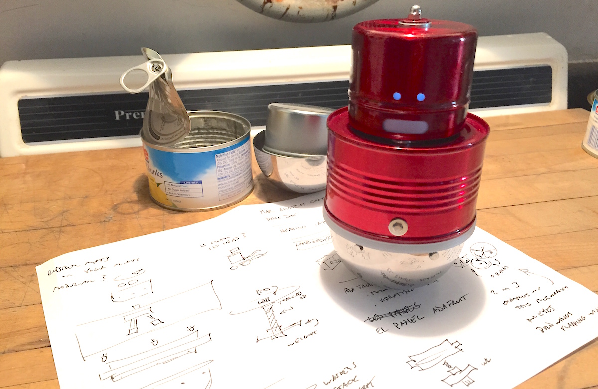
After preparing a tasty pineapple snack, you will have the raw materials to build your own wobbling robot toy. This little guy will shake and vibrate when you turn his head. There is a lot of machining and electronics work in this project, so feel free to tweak the robot recipe if you have better ideas or techniques.

Wobble Bot Recipe GIF

YouTube player

Project Steps

Step 1: Eat Something and Gather Materials

First make some cinnamon roasted pineapple (use canned pineapple chunks), it’s easy to prepare and goes great with vanilla ice cream.

Cans for materials

When you’re finished you’ll have the major building blocks to make the Wobble Bot: a spice container, a pineapple can, and half sphere form.

Remove the paper label and clean out the can. Remove the magnetic backing on the spice container, it peeled off easily for me.

Step 2: Modify Can

Find the center of the can, mark it, and drill a ⅜” diameter hole.

Marking center

Drill center

Use a smooth edge can opener to remove the incredibly sharp lip on the can.

Can top prepCan top prep

Drill ⅜” hole for cables about 1″ from center.

Drill ⅛” diameter holes on each side of the can (two holes altogether), about ⅜” from the lip of the can. These holes will eventually attach the can to the coupling ring.

Step 3: Drill Holes in Half Sphere

Drill six evenly spaced ⅛” diameter holes about 0.185″ from the edge of the half sphere.

These holes will eventually attach the half sphere to the coupling ring.

Bowl with holes

Step 4: Assemble Weight

Attach one lamp nut to the threaded nipple. Stack all of the washers and lamp weight on the threaded nipple and attach the other nut.

Weight

Weight (assembled)

Place the weight assembly inside of the half sphere.

Note: I had to modify the weight a bit on the metal lathe so it would fit properly inside the half sphere. If you don’t have access to a lathe, you can use smaller sized weights.

Weight in base

Step 5: Create Coupling Ring

The point of the coupling ring is to attach the pineapple can to the half sphere. It could be made a few ways, (3D printed, a stack of laser cut rings…) but I turned one out of machinable plastic on the lathe.

Plastic on lathe

One end must fit the inner diameter of the pineapple can (about 3.2″ diam), and the other end must fit inside of the half sphere (about 3.1″ diam).

Coupling Ring

Coupling ring (fitted)

There is also an inner lip of about .2″ that the circular perfboard sits on.

Overall ring dimensions (yours may vary): 3.45″ diameter, 1.25″ height.

Coupling with Perfboard

Mark holes from the pineapple can and half sphere onto the coupling ring. Drill 3/32″ holes and tap 4-40 threads at all of the marks.

Mark two mounting holes for the perfboard and drill ⅛” holes.

tapping-holes_23606157363_oturned-drilled-and-tapped_24124911582_o

Note: I didn’t love working with the machinable plastic. It was finicky and melted a bit. If I had to do it all over again I would probably make it out of Delrin.

Plastic, Machined and Tapped

Step 6: Motor Mount and Wobble Wheel

These plastic motor mounts are very convenient, but you will only need the round barrel part of the mount.

Sand or file a side flat, drill a 7/64″ hole, and tap 6-32 threads.

Motor and Mount

Screw the bracket to the plastic motor mount with a short 6-32 machine screw. Use washers if necessary. Solder jumper wires to the motor and place in mount.

Mounting hardware

Using a machine screw, a few washers, and a nut, place them between the wheel and o-ring (see photo). You will eventually have to fine tune the number and weight of washers used to get the best wobble motion.

Mounted motor

Wobble washer

Step 7: Place Motor Mount

Insert motor mount assembly inside of the pineapple can. The end of the DC motor should fit in the center hole. Mark and drill the hole to mount the bracket to the can. Use a short 6-32 machine screw, washer, and nut to secure the motor mount assembly.

Motor mounted on can

Attach the wobble wheel to the shaft of the DC motor.

Step 8: Create and Assemble Potentiometer Stand

Remove the sliding bracket from the Adjustable Candelabra Socket.

Adjustable Candelabra Socket

Straighten the bracket and rebend it to fit around the potentiometer. Bend the ends so the screw holes will lie flat.

Adjustable Candelabra Socket Top

Bent Candelabra Socket Top

Pot in Bent Candelabra Socket Top

Mark and drill mounting holes in the pineapple can. Assemble using 4-40 machine screws and nuts.

Note: This could also be accomplished by drilling and bending a metal strip. There is nothing special about the bracket from the socket, I just had it laying around on my workbench.

Potentiometer mounted on can

Solder jumper wires to the on/off terminals and a 3 pin jumper to the potentiometer leads. I used a clipped off cable from a burned out servo motor. Tuck cables into the ⅜” hole.

Step 9: Assemble the Head

Mark and drill a ⅛” hole in the center of the spice container.

Hole in head

Drill a ⅛” hole in the center of the potentiometer knob. Place a machine screw inside the knob. Put the knob inside of the spice container, attach with washers and acorn nut.

Head with acorn nut

Drill holes in the spice container for eyes — I drilled two ⅛” holes. After the container is powder-coated, hot glue a piece of vellum to the inside.

Powder coated head

Head lit up

Step 10: Solder and Assemble Circuit

The circuit I used is heavily influenced by Dustyn Roberts’ book Making Things Move, pages 159-162.

Schematic

Potentiometer
DC Toy Motor
555 Timer IC
Capacitor, 0.1uF (2)
Tip 120 Transistor
Voltage Regulator
9 Volt Battery and Connector

Component layout is important. All tall components should be placed along the perimeter of the perfboard or bent to lie flat. Also, there should be no connections made along the center strip (denoted by the blue tape). The 9V battery will eventually be placed underneath the perfboard and this will avoid any potential short circuits. I used male header pins to connect to the motor and the potentiometer.

Notch out one corner of the perfboard for the battery clip.


Assembled circuit

Make sure to disassemble all of the components first and properly clean all of the parts before you powder coat.

Circuit and coupling ring
Mount the circuit into the coupling ring using two 4-40 machine screws and nuts. Make sure to tuck the battery connector underneath the circuit board.

Circuit in Coupling Ring

Step 11: Powder Coat the Parts

You can paint the parts any color, or with any technique, you’d like. I chose to powder coat some of the metal parts using Metallic Red.

Powder coated parts

Everything I know about powder coating I learned from this video.  Make sure to disassemble all of the components first and properly clean all of the parts before you powder coat.

YouTube player

Step 12: Put it All Together

Step 12: Put it All Together

You should have four basic sections/assemblies of the bot at this point: the head, the body, the coupling ring, and the bottom half sphere.

Final components, unassembled

Connect the motor and potentiometer cables from the body to the circuit board mounted in the coupling ring. Then screw them together using two 4-40 machine screws and washers.

Attaching the coupling ring

Connect the 9V battery and double check that the motor is moving and everything is operational at this point.

Attach battery

Tuck the 9V battery under the coupling ring and turn it upside down. Place the weight assembly over the battery and then cover it with the half sphere. Screw in the six 4-40 machine screws.


Machine screw base

Slide the head onto the post of the potentiometer.

Head post on potentiometer

Slide on head

Congratulations, everything is assembled. Your Wobble Bot is finished!

Assembled Wobble Bot

Conclusion

Going further

I eventually added some LEDs inside the head and body. But the effect was a little underwhelming. So I will be working on getting brighter lighting.

I think the wobbling needs a little fine tuning too. Maybe a little less weight at the bottom and a little more weight on the wobble wheel connected to the DC motor. But when the motor is set to the highest setting, I really like the spastic movements and the “evil” sounds it makes.

Happy bot building.

Wobble Bot Recipe GIF