YouTube player

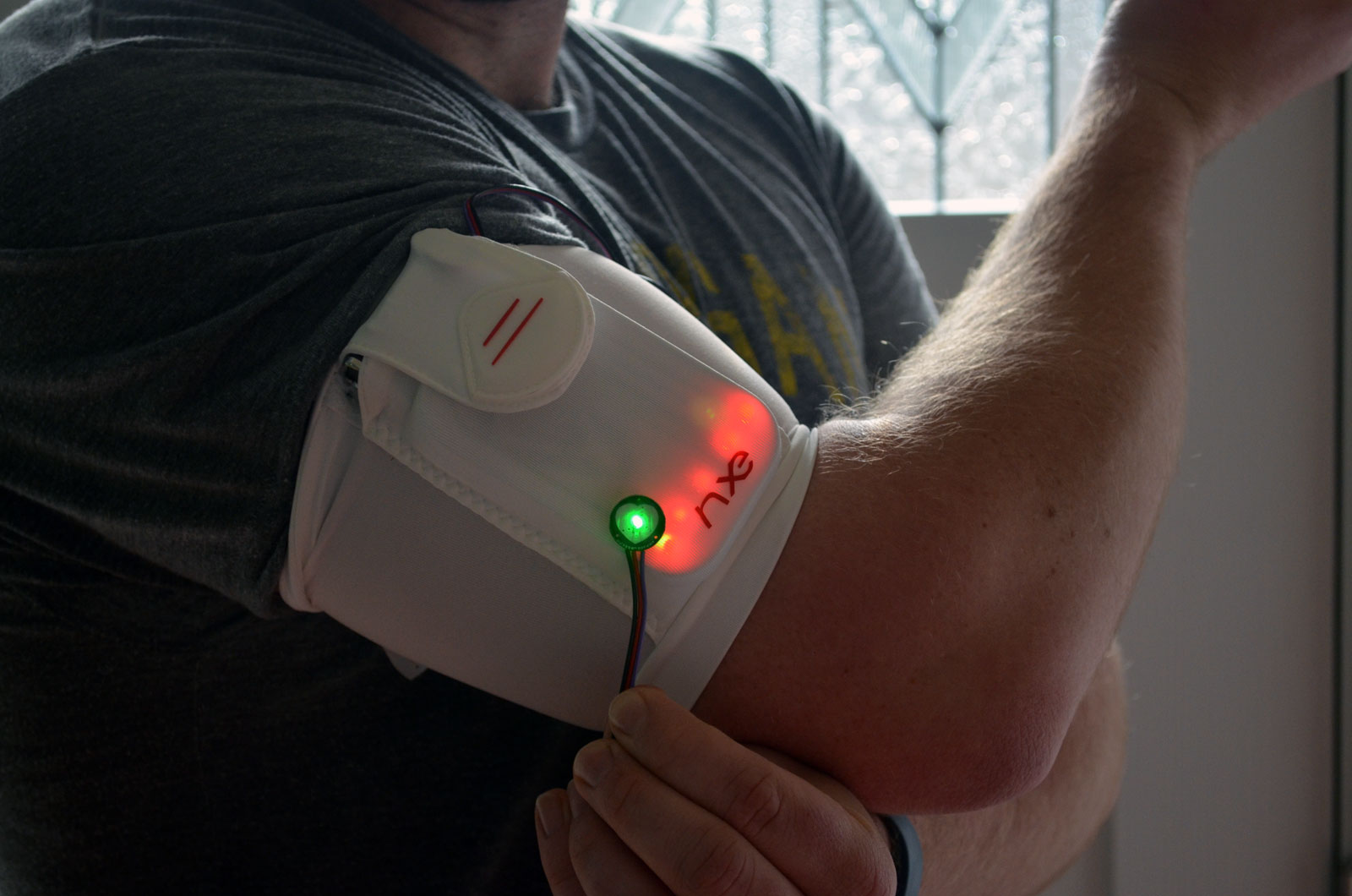
Wear your heartbeat on your arm with the Beatband Sleeve. You’ll combine a pulse sensor with a DIY Arduino microcontroller (and a minty tin) to create this wearable pulse-blinking project. Connect the sensor to your body wherever you get a good pulse reading, and display your heartbeat on the five flashing LEDs. Wear it while you run, play video games, or even while you meditate to show your calming heartbeat ryhthm.

DSC_0815

This project goes through several iterations of the circuit. First you’ll build a fully functional Arduino on a breadboard using the parts from a MintDuino kit. Then you’ll re-flash that circuit with the program for the Pulse Sensor. Finally you’ll transfer the circuit to perfboard and fit it all inside the tin for a fun, wearable project that slips into a sports armband.

DSC_0793c

Project Steps

Build a MintDuino on a breadboard.

Follow the MintDuino tutorial to assemble the MintDuino on a breadboard. It’s a great project in itself if you’re new to building circuits.

The MintDuino chip (ATmega328P with Arduino bootloader) is pre-programmed with a sketch to blink the green LED.

Eventually we will re-flash the MintDuino using an FTDI Friend and the Pulse Sensor code. To upload this code we will interface with the MintDuino through the Arduino IDE software.

You may also need to install drivers for the FTDI Friend.

Prepare the pulse sensor.

Before you can upload a sketch to the MintDuino, you have to tell the Arduino IDE what kind of Arduino to flash. Select the option at Tools → Board → Arduino Duemilanove w/ ATmega328.

Open the code file A_PulseSensor_06.ino but don’t upload it just yet. Let’s prepare our Pulse Sensor first. Check out the Getting Started Guide from the Pulse Sensor website. The guide will tell you that in order to protect the electronics on the sensor, you’ll want to place one of the clear stickers on the front of the sensor and put a layer of hot glue (or velcro) on the back.

Test the pulse sensor and upload the code.

Plug the Pulse Sensor into your breadboard: connect its red wire into the positive (red) rail on the breadboard; black wire into the negative (black or blue) rail on the breadboard; and purple wire into a row connected to pin 23 on the microcontroller IC (integrated circuit) chip.

Now connect the 9V battery’s red wire to the positive rail its black wire to the negative rail. The Pulse Sensor’s bright green LED should light up immediately.

Connect the MintDuino to your computer via USB and the FTDI Friend.

Place the FTDI Friend on the 6-pin header on the breadboard so that the side with the USB port is facing the green LED.

While everything is still connected, click the Upload button in the Arduino IDE. Once the sketch has been successfully uploaded, the green LED on the breadboard will light back up. The green LED on the Pulse Sensor will also light up immediately. If everything is working, we’re ready to build our circuit!

Transfer the MintDuino to perfboard.

The breadboard MintDuino is a classic project in and of itself, and has been used as the brain of previous Weekend Projects, notably the Repeat After Me game. However, for this build we want to transfer it to perfboard so it’ll fit snugly in the mint tin and the armband sleeve.

Follow these instructions to transfer the MintDuino from breadboard to perfboard, with one minor exception: don’t solder the green LED to the perfboard. You’ll replace this component with jumper wires connecting to your 5 red LEDs on the lid (see Steps 9–13).

Prepare the pulse sensor for soldering.

Cut the male header connectors off the end of the Pulse Sensor wire. Leave the full length of the wire available if you’re uncertain how much length you will actually need.

Strip 1/2″ off the end of each wire, and tin the tips.

Solder the pulse sensor.

A printout of the Arduino’s pins helps us remember which pin does what. And a drawing reminds us that the Pulse Sensor’s signal wire will get soldered to A0 (pin 23) on the Arduino’s ATmega IC.

Insert the tinned signal wire to the rail connecting to A0, solder the connection, and trim the lead.

Solder the pulse sensor's power and ground.

Since the ATmega IC is soldered to the perfboard off-center, the center rails provide us with power and ground throughout the circuit.

Clamp the perfboard in the vise with the IC facing down on the lower third of the board. Solder the Pulse Sensor’s positive lead to the top row of the center rails, and solder its negative lead to the bottom row of the center rails.

Trim any excess leads.

Remove the MintDuino lid.

Use needlenose pliers to remove the tin’s lid from the case. This makes it easier to drill into the lid.

Drill holes for the LEDs.

Mark the tin with 5 holes for your LEDs, using a mask or drawing if you wish. You don’t have to place the holes in a straight line, but it looks nice and it makes it easier to wire the LEDs together.

Clamp the tin to a work surface and drill the 5 holes on your marks, using a drill bit slightly smaller than the lens diameter of your LEDs. You want a very snug fit.

Enlarge the holes for the LEDs.

One benefit to using the MintDuino tin rather than an Altoids tin is that the MintDuino tin has a plastic coating. This coating tends to cover the sharp edges of the holes – which helps keep the holes from tearing the armband’s fabric.

Widen the holes just enough to achieve a snug fit for your LEDs, using needlenose pliers, screwdriver, awl, or whatever tool you have handy.

TIP: Work from the top of the tin. Your goal is to enlarge the holes in such a way that any rough edges will be on the underside of the lid. This helps protect the armband.

Mount the LEDs.

Slide the 5 LEDs into their holes from the underside of the lid, orienting them so that all their negative legs are on one side, and positive legs on the other. For example, the third photo here is from later on in the build, but you can see I marked a + and – on the tape to remind me which side was positive and negative.

Hot-glue the LEDs.

Fire up your hot glue gun and evenly coat around the base of the LEDs. You can use some scrap cardboard to spread the glue.

This will leave you with 5 LEDs in a row on the lid of the MintDuino tin!

Solder the LEDs.

Bend all the LEDs’ positive leads so that they touch each other. Also bend all the negative leads so that they touch each other.

Solder all the positive leads together. I did this by going from right to left, bending each LED in the row so that it could hook over on the next one to it. The illustration shows one way of doing this.

Repeat to solder all negative leads together.

TIP: When soldering the LEDs, be careful to not reheat the hot glue too much or get any on your soldering tip.

Connect the LEDs to the circuit board.

Cut one red and one black wire, each about 4″–5″ long, and strip 1/2” from the ends.

Solder the red wire between the LEDs’ positive (+) connection and the perfboard row that connects to pin D13 on the Arduino.

Solder the black wire between the LEDs’ negative (–) connection and the perfboard row connected to the 220Ω resistor.

Insulate the tin and run your wires.

Did you remember to save the cardstock insert for the MintDuino? Great! Place the card in the tin and then place your perfboard on top. You don’t want the circuit to short itself on the tin. The card will reduce the risk.

Pry open one of the tin’s hinge holes just enough to run your Pulse Sensor and battery connector through.

If everything goes according to plan, your perfboard will fit inside the tin with plenty of room to play with.

Close it up!

Push the lid back into the hinges and close it. If everything is still working you can bend the metal hinge tabs back into place.

Put it all together.

Slip the tin into the armband pouch. I highly recommend the NXE ActiveSleeve for this project. Instead of neoprene, it’s made of a stretchy material that allows the light from the LEDs to shine through. You don’t need to modify the armband at all.

Pull the velcro flap closed over the pocket, leaving the pulse sensor leads running out to the side.

Route the leads for the pulse sensor through the center of the armband. The elastic of the armband will hold the pulse sensor in place against your arm.

Position the sensor against your bicep near the inside of your elbow. The excess leads from the sensor can be bunched up inside the armband, underneath the MintDuino tin.

Now watch your heartbeat on your sleeve!