m23_mini-chip-amp-opener
Photograph by Sam Murphy

Skeletal System

Squelette is a see-through amplifier that sounds ridiculously good while showing off your soldering (it looks nothing like a typical audio product). Build it with common materials and enjoy music played through a component you made yourself.

I love to build audio gear: speakers, turntables, preamplifiers, tube amps, transistor amps, and anything else that reproduces music. A few years ago I read rave reviews of an exotic audiophile amplifier based on a National Semiconductor amplifier chip. After more research, I learned that NatSemi’s Overture series of audio amp ICs packs a ton of musical goodness into one robust and flexible chip, combining all the features of a well-designed transistor amp.

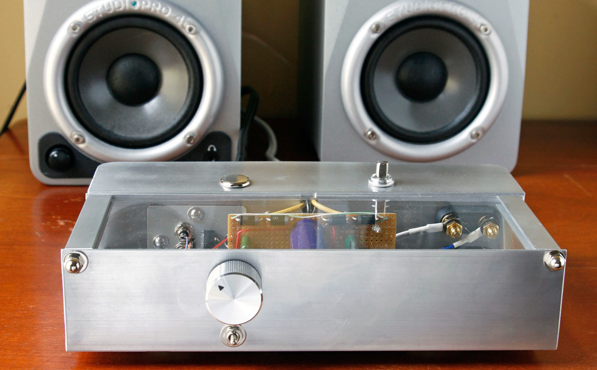
I decided to use their LM1875 chip to make a small, simple stereo amplifier. I dubbed the result “Squelette” (skeleton in French), after mechanical wristwatches that show their internal workings. Squelette is a chip amp in its simplest form: it has 2 source inputs and a volume control, and it puts out a useful 11 watts per channel. Building it requires no exotic parts; I made careful design choices and sourced everything except for the LM1875 from RadioShack and the plumbing aisle at the hardware store. Here’s how you can build your own, from materials costing less than $50 [This figure assumes that you have common components (resistors, capacitors, switches, etc.) already on hand. The cost will be significantly higher if you buy everything new and in small quantities].

Parts photo by Ed Troxell.
Step photos by Ross Hershberger.
Illustration by Timmy Kucynda.

Project Steps

Sound Design Practices

A good design makes every part earn its keep. Here’s how the Squelette amplifier’s common components team up to make a whole that’s greater than its parts.

A: The input jacks connect to the audio source.

B: The power cord connects to one side of a 25.2V 2A transformer. The LM1875 chip can handle larger transformers, but scaling the other components and the heat-sinking design to match would make the amp significantly bulkier, more complicated, and more expensive.

C: The heart of the amp is a small, hand-builtcircuit board. The grid pattern of the board’s perforations lends itself to easy, solder-by-numbers instructions. The power supply components (along the top and middle of the board as shown here) convert AC from the transformer into DC for the amplification circuits.

D: Each of the 2 identical amplification channels is built around a NatSemi LM1875 amplifier chip.

E: Capacitor C1 isolates the chips’ pin 1 inputs from DC, and resistor R1 provides a ground reference.

F: Capacitors C2, C3, C4, and C5 bypass the power supply to the V+ and V– pins of the LM1875, ensuring a low-impedance power source at high frequencies.

G: Resistor R2 and cap C6 form a Zobel filter, presenting a low-impedance load to the output at very high frequencies. This loads down and damps out oscillations and spurious signals outside the audio band.

H: Resistors R3 (on back of board) and R4, AC-coupled to ground through C7, form a global negative feedback loop from the chip’s output pin back to its negative input signal terminal. This feedback sets the overall voltage gain, reduces the output impedance, and reduces internally generated noise and distortion.

I: The circuit board is housed in a cabinet made from stock aluminum angle and plexiglass. The aluminum attaches to the LM1875 chips as a heat sink, as well as serving as the circuit ground. The plexiglass lets you see the circuitry.

J: All ground connections run directly to one shared “star” ground, a large loop of wire centered on the back of the PCB that connects to the cabinet. This wiring prevents interactions between circuit features that could cause noise and instability.

K: The 3P2T (triple-pole, double-throw) input selector switches both the signals and the grounds of 2 input devices, to completely isolate the deselected input device. This avoids ground currents and noise that can come from connecting different inputs’ grounds together. Wired for “center off,” the switch also lets you mute the amp without changing the volume setting.

L: Two acorn nuts at the upper corners of the chassis let you expose the amp’s innards to open air, and 5 more screws let you remove the Squelette’s circuitry from the chassis completely, without unsoldering.

Build the circuit board

This board looks complex, but each LM1875 chip contains 46 transistors; imagine hand-wiring all of those!

Cut a 33×15-hole piece of perf board, then sand the edges. Scour the copper side with a Scotch-Brite pad and wipe with alcohol. Tape a cardboard frame around the edges and label the rows 1–15 and the columns A–AG, with the origin at upper left on the component (non-copper) side.

NOTE: You can download the schematic diagram for the Squelette here.

Start with the power supply. Connect the following hole pairs with diodes, cathode side (marked with a line) listed second: B1 to G1, H1 to M1, X1 to S1, and AD1 to Y1.

On the copper side, jumper G1 to H1, X1 to Y1, and M1 to S1. Clip the leads at H1 and X1 off to ½” and bend them under in a tight loop. Clip all other leads off completely.

TIP: If any holes are too small, ream them from the component side with a needle file, a knife point, or (fastest) a Dremel tool with a tapered diamond bit.

Strip some 24-gauge wire, thread it through A1, and solder it in back to bridge A1 and B1. Route it over the 4 diodes, and strip, thread, and solder the other end to connect AE1 and AD1.

Stuff a 4,700µF cap into P3 (+) and P6 (–) and another into P10 (+) and P13 (–). Jumper S1 to P3. Electrolytic capacitors have the (–) terminal labeled.

Build the circuit board (cont'd)

On the component side, pass a 24-gauge wire through AF1 and connect to AD1. Route it between rows 1 and 2, then down between columns S and T. Thread the other end through S14, insulated, then cut, strip, and connect only to P13.

Connect P6 to P10 in back with a raised loop of bare 18-gauge wire. This is the star ground node, and a lot of wires attach here, so leave some room.

To test this circuit, clip-lead (alligator jumper) the transformer’s secondary center tap lead (black) to the 0V star ground at P6/P10, and its secondary (yellow) leads to X1 and H1. Temporarily solder one side of the fuse holder to one of the transformer’s primary leads (black) and tape the joint. Insert a 500mA fuse. Split a power cord (not plugged in), connect it between the free side of the fuse and the free primary transformer lead, wrap with electrical tape, and use a switched power strip to apply power to the transformer.

If nothing sparks or pops, measure the DC voltages across both capacitors. You should get around –18V from P10 to P13 and around +18V from P10 to P3. If the voltages read 0V, check the fuse. If it’s blown, there’s a wiring error. If the voltages check out, turn it off and clip a 22K resistor between P3 and P13 to bleed off the charge on the caps.

Build the circuit board (cont'd)

Stuff and solder the following left channel components:

  • LM1875 into D13–H13, perpendicular to and facing the center of the board (pin 1 in H13, heat-sink side out)
  • 1K resistor into H15, K15
  • 22µF capacitor into L15 (+), L14 (–)
  • 22K resistor into J10, J13
  • 1µF cap into I8, I13.

On the back of the board, solder K15 to L15 and clip off. Solder H15 to G15. Solder J13, I13, and H13 together and clip off. Clip the other leads except for I8, J10, and L14.

Stuff and solder a 0.1µF cap into G10, G14; and a 100µF cap into F8 (+), F9 (–). On the back, bend lead F9 down and solder it to F13 and G14. Bend lead G10 up and solder it to F8. Clip the other leads, except for F8.

Stuff and solder a 1Ω resistor into D9, E14; and a 0.22µF cap into D5, D8. In back, solder E14 to E15, and D8 to D9. Clip except for D5 and E15.

Stuff and solder a 100µF cap into C12 (–) and C13 (+); and a 0.1µF cap into A9 and A13. Bend lead C12 up to A9 and solder, then solder A13, C13, and D13 together.

Build the circuit board (cont'd)

Use separate jumpers to wire A9, D5, F8, J10, and L14 to the ground wire loop in back. Put a red 24-gauge jumper through L3 from the component side and connect it to P3. Pass the other end through B14 and connect it to D13. Put a green jumper through O15 from the component side and connect it to P13; pass the other end through F12 and connect it to F13.

Finally, connect a 20K resistor (or a 22K and 220K in parallel) on the copper side between G15 and E15, making sure it doesn’t project past the edge of the board. This is the feedback resistor. Clip off its lead at G15 and leave its other lead in place.

Stuff and solder the following right channel components
(just like building the left channel):

  • LM1875 chip into AC13, AB15, AA13, Z15, and Y13, perpendicular to and facing the center of the board (pin 1 in Y13, heat-sink side out). The chip should clear the bottom edge of the PCB.
  • 1K resistor into AC15, AF15
  • 22µF cap into AG14 (–), AG15 (+)
  • 22K resistor into AE10, AE13
  • 1µF cap into AD8, AD13

On the back of the board, solder AF15 to AG15 and clip off. Solder AC15 to AB15. Solder AE13, AD13, and AC13 together and clip off. Clip the other leads except for AD8, AE10, and AG14.

Stuff and solder a 0.1µF cap into AB10 and AB14; and a 100µF into AA8 (+) and AA9 (–). On the back, bend lead AA9 down and solder it to AB13 and AA14. Bend lead AB10 up and solder it to AA8.

Build the circuit board (cont'd)

Stuff and solder a 1Ω resistor into Z14 and Y9, and a 0.22µF cap into Y5 and Y8. In back, solder Z14 to Z15, and Y8 to Y9. Clip except for Y9 and Z15.

Stuff and solder a 100µF cap into X12 (–) and X13 (+), and a 0.1µF cap into V9 and V13. Bend lead X12 up to V9 and solder it, then solder V13, X13, and Y13 together.

Use separate jumpers to wire V9, Y5, AA8, AE10, and AG14 to the ground wire loop in back. Put a red 24-gauge jumper wire through U3 from the component side and connect it to P3; pass the other end through U13 and connect it to Y13. Put a green jumper through S14 from the component side and connect it to P13; pass the other end through AA12 and connect it to AA13.

For the right channel feedback, connect a 20K resistor (or a 22K and 220K) on the back between AB15 and Z15. Clip off lead AB15.

Test the amp

For the power indicator light, stuff your favorite color LED into AC3 (anode, longer leg) and AD3 (cathode). Bend and solder the cathode lead to AD1. Stuff an 830Ω, ½W resistor into Z3 and V3, then solder V3 to the ground wire loop, and Z3 to AC3.

The circuit board is done now, and the only unconnected leads remaining should be I8 (left channel input), E15 (left channel output), AD8 (right channel input), Z15 (right channel output), X1 and H1 (AC input), and the ground at P6–P10.

To set up testing, hook up the transformer to the power supply as in Step 3 Bullet #3. Clamp a heat sink to the tab of each LM1875 chip, making sure they don’t touch anything conductive. For dummy loads, clip-lead a 10Ω–25Ω, 10W resistor from E15 to ground, and a second resistor from Z15 to ground. Connect AD8 to I8. Connect I8 to ground for the moment.

Power up the circuit as in Step 3 Bullet #3. The power LED should come on. Measure the DC voltage across each dummy load resistor. If it’s over 0.05 volts, power down and look for wiring errors.

For signal testing, disconnect I8/AD8 from ground and connect them to any signal generator source with a volume control. Power the circuit back up and test across the load resistors, measuring AC voltage this time. Briefly increase the volume of the input, and look for the voltage to read up to about 9V AC output. But keep all signal testing brief, to avoid overheating the chips. If you have an oscilloscope, look for clipping at about 25V peak-to-peak. Reduce the signal to 1V AC output on one channel, and then test the other channel; it should also measure 1V AC. Switch the meter to DC and confirm that both channels measure 0V DC. Try a speaker in place of the load resistor to make sure the output signal sounds like clean sine wave. If it all checks out, your board is done and working.

Make the cabinet

Download and print the mechanical drawings. Part A is the chassis front, B is the inside back, and C is the outside back. Parts D and E are rails that hold the plexiglass ends and top.

Cut three 9″ lengths of the 2” aluminum angle and four 3″ lengths of the 3″×½” aluminum channel. Sand the edges smooth.

To protect the aluminum and mark the patterns for drilling and cutting, cover the surfaces with masking tape. Transfer the markings from the drawings.

On Part C, position the transformer and check the clearance between the switch and transformer underneath. Adjust the position of the switch hole to suit your switch, and mark it.

Time to drill. Use a sharp punch and a hammer to dimple the center of each hole to be drilled. Drill the smallest holes first.

TIP: Some holes need to align for assembly: the row of four t” and Y” holes on parts A and B; the 1″ holes in the D spacers and the bottom corners of A and B; and two Y” holes on parts B and C. For these, drill one part, clamp it up to the other part, and mark the hole locations with a Sharpie. Punch and drill on your marks, and the holes will match up. This is cheating but it works.

Make the cabinet (cont'd)

For larger holes, drill a small hole first to make the bit easier to center. You can also cut large holes with a step bit (aka castle bit or unibit).

Use a tapered reamer or round file to open the large holes up to their final size. Deburr the small holes with a large drill bit or chamfering tool. Deburr the large holes with a round file. Holes C at the bottom of part A must be completely smooth. Any burrs there might poke into and short out the LM1875 chips.

For the square hole on part B, the input panel, you can drill a 3″ hole and use a ¼” metal nibbler to cut the perimeter. Finish the hole with a flat file.

Part C has 2 large areas to cut out. Saw these with a hacksaw or band saw and deburr. Make two 1″×¼” shims out of the cut-out material. These will fill a gap between parts B and D.

Make the cabinet (cont'd)

For the long slots in parts B and C, drill a ¼” hole at the end, and saw up to the holes, making ¼” slots with round ends.

Assemble the metal parts to check for hole alignment: two 3½” screws with acorn nuts at the tops of parts A and B, through rails E; #8-32×½” screws and nuts through the matching Y” holes on A and B, and B and C; and #4-40×3/8″ screws securing rails D to the bottom corners of A and B. Adjust the positions of any off-center holes with a needle file.

Cut 6″-thick plexiglass into one piece 8½”×24″ (for the top) and 2 pieces 24″×1½” (for the sides). Notch out the lower corners of the side pieces so they clear the nuts in the D rails. Test-fit these pieces and trim to fit.

For the input terminal panel, cut a 1½”×2″ piece of Formica or other thin, stiff plastic. Tape it inside the input terminal cutout on B, then transfer the screw hole positions and cutout shape to the plastic with a Sharpie.

Drill the 3 smaller holes for #4 screws (0.100″) and the larger hole for the #8 screw (0.16″) to mount the transformer. Find positions on the cutout area where the input jacks will not touch part B’s metal, then drill the plastic and install the input connectors there.

Connect the off-board components

Test-fit the volume knob onto the dual potentiometer shaft. Cut the shaft to length, being careful to keep metal bits from getting inside the potentiometer.

Referring to the photo of the potentiometer and 3P2T switch at right (and the tip below), use 4″ wires to connect the following input jack and switch terminals: input 1 left to switch 7, input 1 right to switch 9, input 1 ground to switch 8, input 2 left to switch 1, input 2 right to switch 3, and input 2 ground to switch 2.

Use 3″ wires to connect switch 6 to volume pot 4, switch 5 to volume pot 3 and 6 (both), and switch 4 to volume pot 1.

With 6″ wires, connect volume pot 3 and 6 to the star ground wire on the PCB, volume pot 5 to PCB lead AD8, and volume pot 2 to PCB I8.

TIP: Recall that with headphone plugs, the tip is the left channel, the ring is the right, and the body or “shield” is ground.

Cut the socket end off your extension cord. Near the plug, cut out a section of the live wire (the wire connected to the plug’s narrower prong). Splice in the inline fuse holder with enough slack so you can open it up, and insulate these solder joints with heat-shrink tubing. Write “½ A” on the fuse holder, or otherwise label it in case the fuse is lost.

Slide cable sleeving up over the fuse holder and position it so it can be pushed back for changing the fuse. Fix one end of the sleeve to the cord with shrink wrap or a zip tie, and the other end with a loop of double-sided velcro.

Install the speaker terminals, power switch, and transformer on parts B and C, running the transformer secondary (yellow and black) wires in through the slots. Temporarily screw the PCB to part B with screws through the LM1875 tabs. Bend the 2 yellow leads to the hooked diode leads H1 and X1, and carefully mark where they meet. Do the same for the 1 black center tap lead to connect to the ground wire loop at P6–P10. You’ll connect these 3 wires later, but their lengths are critical because they support the upper edge of the PCB.

Measure and note the distances from the PCB ground to the speaker terminal black posts, and from the speaker terminal red posts to the amplifier outputs at E15 and Z15. Remove the PCB from the chassis and set it aside.

Connect the off-board components (cont'd)

Test-fit the power line cord to the chassis with a nylon P-clip on the transformer mounting screw under the switch. Measure, cut, and solder the cord’s neutral (wide prong) side to one transformer primary lead, and its live (narrow prong) side to one switch lead. Solder the other switch lead to the remaining transformer primary lead. Insulate all solder joints with heat-shrink, and refit the power cord and P-clip.

Disassemble everything and then cut and strip the transformer wires (yellow and black) where you marked them in Step 11 Bullet #8. Flip everything over and solder the transformer leads to the PCB.

Solder two 18-gauge stranded wires to the PCB’s ground wire loop and run them to the speaker terminal black posts, trimming their lengths and connecting them to the posts with spade terminals crimped and soldered onto the wires. Similarly connect 2 more 18-gauge wires between the PCB’s E15 and Z15 positions and the speaker terminal red posts. Be careful not to damage the feedback resistors soldered to those output terminals.

Crimp and solder a spade lug to one end of a 2″ length of 18-gauge stranded lead, and solder the other end to the PCB’s star ground loop P6-P10. This will be the ground connection, screwed down at the transformer’s right mounting screw. The circuit is now electrically complete. You can test it again to make sure it still works.

Assemble everything

Put two #8 screws through the plastic feet, pass them up through the Y” holes from underneath parts A and B, and secure them with nuts on top. Part A overlaps on top of part B. Install rails D as in Step 10 bullet 2, filling the gap between B and D with the 1″×¼” shims you cut in the last bullet point of Step 9.

Install the speaker binding posts.

Place TO-220 mounting insulators over the t” holes on part A, where the chips will bolt down. Use thermal grease if they’re mica insulators.

Carefully place the assembled electronics into the A/B assembly. Secure the input switch and volume control to the front of A with nuts. Install the volume knob. Install the three #4 screws that hold the input panel to B, and nut them on the back.

Slide part C between the transformer and part B. Install the power switch in part C. From the back, pass a #8×½” screw through the transformer mounting hole, parts C and B, and the input panel. Pass #8×½” screws through the P-clip holding the power cord, the transformer mounting hole, and parts C and B on the speaker side. Nut these 3 screws on the inside, trapping the PCB ground wire lug under one nut to ground the PCB to the chassis.

Assemble everything (cont'd)

Screw down the LM1875 chips with #6 nylon screws from below and metal nuts on top. Don’t use metal screws. The chip tabs must be electrically insulated from the chassis.

Connect the speaker ground leads from the PCB to the black speaker terminals. Connect the speaker signal leads to the red speaker terminals, right to lower and left to upper.

Drop the plexiglass side panels in place in rails D. They’re left loose for airflow.

With washers, pass the #8×3½”screws through the upper corner holes in parts C, B, and A from the back. Install washers and acorn nuts on them at the front. Slide one rail E over the long screw from the side. Tighten the nut on the screw to hold the E rail in place. Slide one end of the plexi top into the E rail. Slide the E rail over the other end and tighten the long screw’s nut to hold it in place.

You’re done. Hook it up and take it for a spin!

Use it

Simple Power Amp
If you plan to use a single signal source, you can omit the 3P2T source selector switch and wire your input connectors directly to the volume pot.
And if your source has a volume control of its own, you can build the Squelette as a plain power amp by replacing the 100K volume pot with a 100K resistor to ground for each channel.

Headphones
There’s no headphone jack in this build, but you can add one by connecting it to pin 4 of each chip through 150Ω resistors in series with the signal leads. This configuration limits current, preventing you from accidentally smoking your ’phones. Insulate the headphone jack body from the metal chassis and ground it to P6–P10.

Radio
A good mini amp deserves a good mini source. For FM stereo, AM, and shortwave listening, I recommend Grundig’s compact radios. RadioShack sells the high-performance G8 model for $50.

Speakers
Quality speakers make a huge difference to music reproduction. I polled the speaker experts on Audiokarma for suggestions on good-sounding compact speakers under $250. We recommend the JBL Control 1, the Paradigm Atom, the PSB Alpha Series, and the Sony SS-B1000. Any of these will provide clean, well-balanced sound from your Squelette.
The basic Squelette circuit can be used for other applications as well. Install a chip amp inside a speaker cabinet. Convert an old tube table radio to a powered iPod dock. Make an amplifier to match your customized Chumby.
Build your own steampunk amplifier, complete with brass meters, knife switches, a japanned steel cabinet, and a fly-ball governor for voltage regulation. Please! I so want to steampunk one of these, but I have always opted for minimalism.