Filabot_wee

Is your 3D printer burning through filament? Guess what — there’s no reason it has to be expensive. With a filament extruder, you can make your own filament from plastic pellets costing as little as $3–$5 a pound, saving you up to 90% compared to purchasing filament from online sellers.

We launched Filabot on Kickstarter with the goal of recycling waste plastic into something useful. The project has evolved into a family of machines, the first of which is our new Filabot Wee, which melts inexpensive PLA or ABS

pellets and extrudes high-quality filament in 1.75mm and 3mm diameters.

The Filabot Wee is designed to use as few parts as possible while still making quality filament, quickly, for fused-filament fabrication (FFF) 3D printers. We sell it fully assembled, or as a complete kit. In addition, the Wee is an open hardware project under the terms of the BY-NC-SA Creative Commons license, and we’re making our plans freely available so that anyone can build their own. Here’s how.

Downloads

Filabot Wee Filament Extruder Specifications

  • Maximum temperature: 350°C
  • Extrude rate: 5ipm–20ipm, depending on plastic and diameter
  • Feed screw speed: 35rpm
  • Input power: 120V AC or 220V AC
  • Power draw: ~300W
  • Footprint: 17″×7″×8″

What will the next generation of Make: look like? We’re inviting you to shape the future by investing in Make:. By becoming an investor, you help decide what’s next. The future of Make: is in your hands. Learn More.

Project Steps

Check or make your parts

If you bought a kit, check the Bill of Materials to make sure all the necessary parts are provided, and contact Filabot if anything’s missing.

Scratch builders, you’ve got some wood- and metalworking in your future. To get started, click on the above parts drawings.

Using a laser cutter or a fine woodworking saw, cut the enclosure’s top control panel and back wall from the 6mm plywood. Using heavier saws, cut the 1/2″ plywood to make the base and the side panels.

Cut, drill, and bend the 11-gauge sheet metal, per the drawings, to make the motor mount, back chamber support, front chamber support, and 2 side brackets. Cut and bend the hopper from 18-gauge sheet metal, and cut the thrust bearing plate from 1/4″ sheet metal. We cut our parts on a plasma cutter, and it’s really the way to go; a local CNC service may be able to do this for you.

Now to the machining. Chuck the 1018 steel rod stock in a metal lathe or mill to cut the basic profiles for the motor coupler, shaft collar, and large nozzle. Then mill the hex edges on the large nozzle. Go back to your lathe and/or mill to cut the 1045 steel rod as needed to fabricate the chamber, and the aluminum rod as needed to fabricate the chamber surround (aka heater holder). Drill and tap threads on all parts as indicated by the drawings.

Finally, drill out the 2-16 hex bolts to make 4 nozzles: 1.75mm and 3mm for the 2 test nozzles, and 1.35mm and 2.5mm for the 2 “undersized” nozzles, which are the ones you’ll actually use most of the time.

Attach the motor shaft coupler

With the parts in hand, you can move on to assembly. First, attach the motor coupler to the gearmotor shaft, using two of the M6-1mm cap screws. Tighten them with an Allen wrench.

Bolt the motor to the motor mount

Attach the U-shaped motor mount to the gearmotor using four 1/4-20×1/2″ bolts with washers. Thread these bolts in loosely for now; you’ll tighten them completely later.

Weld the extruder chassis (optional)

If you’re building from scratch or from the unwelded kit, follow the Extruder Welding Diagram to weld the chassis together from the chamber, the chamber supports, the thrust bearing plate, the side brackets, and the hopper.

Mount the feed screw and thrust bearing

Slide the feed screw into the extruder chamber from the front, until its shank peeks out the back. Insert the shaft collar into the thrust bearing as shown, then hold them inline with the feed screw and push the screw the rest of the way in. When it stops, the shank should stick out past the bearing about 3/4″. Tighten the collar’s cap screw with an Allen wrench.

Mount the motor

Slide the motor coupler onto the feed screw, making sure that one of its cap screws lines up with the flat spot on the feed screw shank. Tighten the cap screws with an Allen wrench.

Use four 1/4-20×1/4″ hex bolts, 4 washers, and 4 nuts to attach the motor mount to the extruder. Before the bolts are tight, pull back on the whole gearmotor to take up any slack in the thrust bearing. Then tighten the bolts with two y” wrenches, one on each side.

Once these 4 bolts are in, cinch down the 4 motor bolts. Saving these for last helps with shaft alignment.

TIP: The motor mount may be spaced a bit away from the chassis; squeeze them together with vise-grips if needed to start the bolts.

Install the heater

Apply a small bead of thermal paste around the heater to help with heat transfer. Then slide the heater into the smaller lengthwise hole in the heater holder and tighten a setscrew just enough to hold it in place.

Apply thermal paste to the inside of the larger hole, then slide the heater holder onto the chamber with the heater wires sticking out the back. Insert a setscrew into the side hole as shown, and tighten.

Temperature probe and insulation

Screw the temperature probe into the top hole in the heater holder, using thermal paste to ensure a steady reading. Tighten with an adjustable wrench.

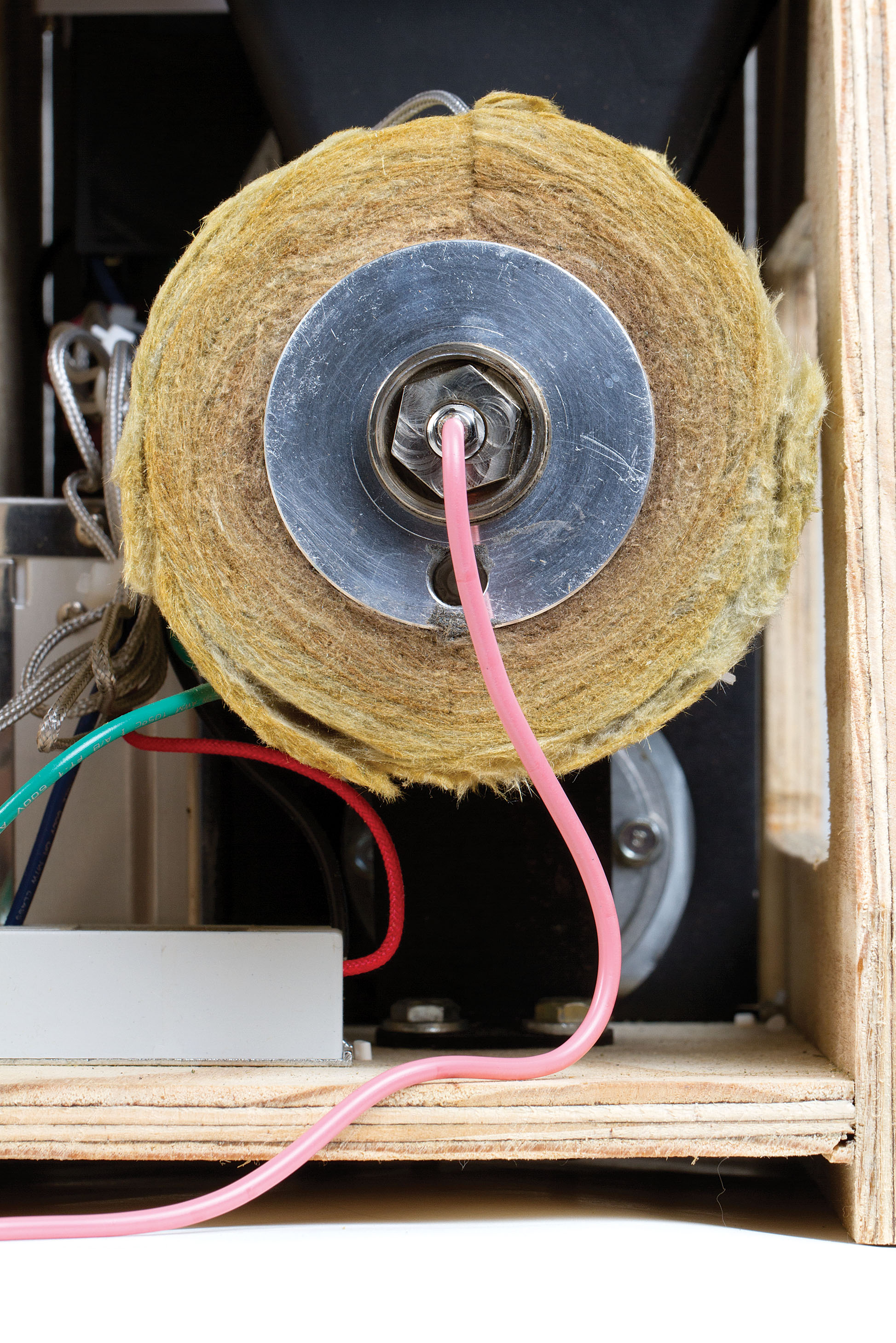
Zip-tie the insulation around the heater holder with the seam on top, and trim the zip ties.

Finally, screw the large nozzle into the front end of the chamber.

Mount the base

Fix the relay and power supply to the base using 1/2″ wood screws as shown. Bolt the extruder to the base using 1/4-20×1″ bolts, washers, and hex nuts.

Build the enclosure

Turn the base on its side and attach the right side wall (with the big cutout) using three #4×1″ wood screws through its face into the base edge. (This is the “right” side wall with respect to the front of the extruder.)

Flip the unit upright and use two 1″ wood screws to mount the top panel to the right side wall.

Position the rear wall (with the power inlet cutout and zip-tie holes) between the base and the top panel, and secure it with finishing nails through the top panel and side wall.

TIP: Position the base 1/2″ up from the side walls’ bottom edges so they’ll act as feet.

Wire the system

Follow the schematic above to wire the machine and mount the switches and power connector.

To connect the PID temperature controller, run its wires from inside the Filabot, through its white mounting frame, and out through the hole in the top panel. Connect the wires, then guide the temperature controller and mounting frame back into the hole.

Use 2 zip ties to mount the terminal strip to the rear wall, passing them through the precut holes.

Close it up

Install the left side wall with 3 screws through its face into the base, and 2 through the top panel into its edge.

Now Make Filament!

Place the machine on a tabletop, with its nozzle at the edge.

Turn all switches off. Plug in the Filabot, then turn on the Main Power and Temperature Controller switches. To use the temperature controller, follow the bundled manual. PID temperature controllers do some calculus to predict ups and downs and keep temperatures extremely smooth.

Set the temperature for the plastic you’re extruding and wait until the chamber reaches the desired temperature. Only extrude at the proper temperature; running the machine too cold can damage mechanical components.

ABS extrusion temperatures range from 150°C to 180°C. PLA extrusion temperatures range from 130°C to 160°C. The temperature controller measurements will read slightly lower than the actual extrusion temperature. Adjust as needed for performance.

Put pellets in the hopper, and turn on the Feed switch. The first time you run the extruder, the first 1/2lb of filament or so may have a gray color from the oil used during machining. We don’t recommend printing with it until the filament comes out clean.

As the filament starts to come out, guide it onto the floor below and lay the first few feet in a circle. This will make the filament naturally coil on the floor. From this point, just keep the hopper topped off and filament will keep pumping out. Every so often, check the filament for air bubbles. If they appear, lower the temperature as needed to eliminate them.

Once you’re done making a batch of filament, turn all the switches off, unplug the power cord, and leave it unplugged until the next usage.

The Filabot Wee has been tested with ABS and PLA, and can make both 1.75mm and 3mm-diameter filament. Most of the time, you’ll use the “undersized” nozzles; these are drilled smaller to compensate for plastic’s tendency to swell during extrusion. The test nozzles drilled at exactly 1.75mm and 3mm are included so that if you’re extruding a different grade or type of plastic, you’ll be able to measure the swelling and make your own nozzles to compensate.

You can rig your own reel or other method of collecting fresh filament as it extrudes, or try our Filamatic spooling kit. It has a 12rpm gearmotor and a custom circuit board and uses 2 photo gates as switches. It works with both 1.75mm and 3mm filament diameters and can handle any extrusion rate.

CAUTION: The Filabot may work with other plastics, but if you experiment, be sure you understand any potential hazards. PVC, for instance, may emit toxic fumes during extrusion.