Photo by Hep Svadja
Photo by Hep Svadja
m55_cover_hirez
Read articles from the magazine right here on Make:. Don’t have a subscription yet? Get one today.

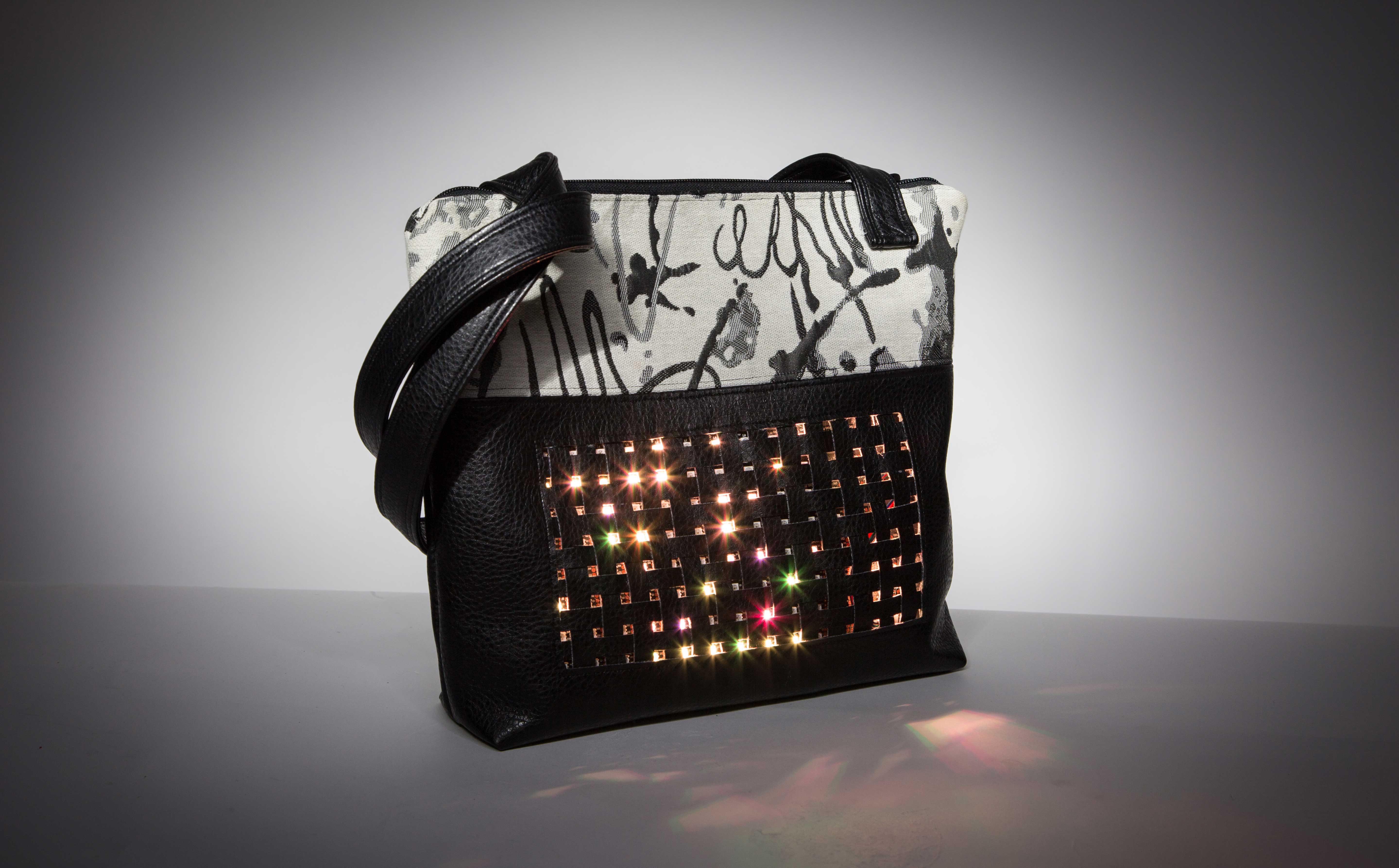
Here’s a dazzling, fun accessory for an evening out that’s also a great conversation starter — a fabric-topped vinyl handbag with a removable, Bluetooth-connected, full-color LED matrix.

It’s bright, beautiful, and interactive, controlled by a smartphone app that sets the display of different low-resolution animations and scrolling text — it can even receive data from Twitter in real-time. And because it’s removable, it can easily be used in another wearable project, such as a messenger bag or jacket.

The most challenging part of this project was coming up with a design that organically and seamlessly integrated the LEDs into a handbag that’s attractive on its own merits. About a year ago I created my first Twitter purse with a 10×6 matrix but I wanted a better-looking one. So here’s version 2.0, with a new, woven matrix cover and a bigger, 14×8 LED matrix. I’m proud of the outcome and really enjoy taking it with me when I go out.

YouTube player

How can a purse talk to Twitter? Below, I’ll show you two different ways to program it: one using the Adafruit.io and IFTTT cloud services, the other using a dedicated Raspberry Pi running Mosquitto server and Node-RED.

Make Your Tweet-Powered LED Handbag

If you have some comfort with a sewing machine, I estimate it’ll take you 6–8 hours to make the bag, 8–10 hours to build the electronics, and maybe another 6–8 hours to do all the programming.

Project Steps

1. MAKE THE LED MATRIX

Step shots by Debra Ansell
Figure A. Step shots by Debra Ansell

Cut the 2-meter APA102C RGB LED strip into 8 short strips of 14 LEDs apiece, using a wire cutter to cut along the lines between the soldering pads (Figure A). Leave the first 14 connected to the JST “in” connector. (Usually, arrows on these LED strips indicate directionality; data flows in one end and out the other end.)

There will be 8 LEDs left over, which you can discard or use for another project — but save the JST connector from the “out” end. You’ll use it later in the project.

TIP: Most LED strips have a join every ½ meter. The spacing at this join is different and can ruin the symmetry of the matrix, so cut your strips from between the joins.

Figure B
Figure B

Cut a piece of clear vinyl backing about 28cm×14cm. Larger is fine; you can always trim it later. Leave a margin of vinyl at least 1cm wide around the LED strips. Use a fine-point marker to draw 8 parallel lines spaced 1.6cm apart (Figure B).

Line up the LED strips on the vinyl, orienting them in a back-and-forth pattern so that current and data can flow out the end of one strip, into the beginning of the next. Be sure the strip that’s still connected to the “in” JST connector is the first row of your matrix. Peel the backing off each LED strip and press it onto the vinyl.

step2_pic2

2. SOLDER AND TEST THE MATRIX

Cut the 26 AWG stranded wire into short lengths to connect each LED strip to its neighbors. Tin the pads on the end of each strip, and the ends of each wire, before soldering. Be careful that the stranded wire doesn’t spread out and make contact with a neighboring solder pad.

Figure C
Figure C

Somewhere in the middle of the matrix, solder on an extra wire each for power and ground to the end of one of the strips and leave them loose (Figure C). These will be used to supply power to the matrix.

Figure D
Figure D

Now test your connections. Connect your matrix to an Arduino Uno (5V, GND, pin 4 for data, pin 5 for clock) and run Adafruit’s test sketch from Github to make sure all the LEDs light up correctly (Figure D).

Figure E
Figure E

Once tested, use a hot glue gun to cover the solder joints (Figure E). This provides strain relief for the wires and also prevents any stray strands from coming loose and causing a short.

3. ATTACH THE POWER JACK

Figure F
Figure F

Solder a 2.1mm barrel-jack connector to the power and ground wires you left loose on the last step. Use shrink tubing around the connector to provide strain relief on the wires (Figure F). This barrel jack port can now be connected to any 5V regulated supply to power the LED matrix. A 5V lipstick phone charger in conjunction with a USB-to-barrel-jack cable works well as a portable power source.

step4_pic3

4. CONNECT THE MICROCONTROLLER

Figure G
Figure G

Solder connections to the Adafruit Feather M0 Bluefruit board and the logic converter as shown in Figure G. Solder the 4 wires leading off-board to the mating JST connector you saved in Step 1, so you can plug and unplug your matrix.

Figure G. schematic
Figure G. schematic

5. MAKE AN ENCLOSURE


Find a box or make a protective housing for the electronics. I 3D-printed a box with a hole to allow a micro-USB connection to the Adafruit Feather. You can download the design files for the box from GitHub.

6. WEAVE THE LED MATRIX COVER


The matrix cover is made by weaving thin strips of vinyl (or leather) between the LEDs. The spacing between LEDs is 1.1cm, so you’ll need 24 strips 1.1cm wide. Mark the spacing on the wrong side of the vinyl and cut the strips with a rotary cutter and ruler (recommended), or with fabric scissors.

Figure H
Figure H

Lay out the horizontal vinyl strips between the LED rows, with one strip above and below the top and bottom rows as well. Then weave vertical strips between the horizontal ones so that only the LEDs show through the holes in the woven grid. It’s easiest to do the weaving at the end of the horizontal strips, then slide the vertical strips into position (Figure H). Be sure there are strips all around the perimeter.

step8_pic2

Once the grid is complete, use a toothpick to apply small dabs of fabric glue to secure the vinyl strips in place. Start with a corner of the grid, and work your way around the perimeter, very lightly tacking all the overlapping strips to each other (not to the LED matrix). Once the perimeter is glued, tack enough of the strips in the center of the grid so that they won’t slide around when the grid is lifted. Let dry at least 1 hour, then lift it off the LED matrix and trim the excess fringe (Figure I).

Figure I
Figure I

7. CUT THE HANDBAG PIECES

While the glue on the grid is drying, cut the pieces for the handbag body as follows: vinyl 16×9½” (2), accent fabric 16″×5½” (2), lining fabric 16″×14″ (2), and 1 pocket made from the lining fabric, sized as you desire.

8. SEW THE GRID TO THE FRONT PANEL

Figure J
Figure J

Choose one of the vinyl pieces to be the front of the handbag. Then cut a window just large enough to display all the LEDs in the matrix. The outer perimeter of the LEDs in my matrix is about 21.8cm wide by 11.7cm high, but you should measure yours in case there are variations. Draw a rectangular hole, matching your perimeter, about 1½” down from the top and centered, and then cut it out (Figure J).

step12_pic1

On the wrong side of the vinyl, draw a light line of fabric glue around the window and glue your vinyl matrix cover into place. Allow the glue to dry at least 1 hour and then sew around the perimeter of the hole with a 1/8″ seam to hold the matrix cover in place (Figure K).

Figure K
Figure K

TIP: A leather needle and walking foot attachment for your sewing machine will make sewing several layers of vinyl together much easier.

9. ADD THE MAGNETIC SNAPS

step13_pic2
Figure L

Magnetic snaps let you remove your LED matrix and use it in other projects! Align your LED matrix with the vinyl grid, then peel the backing off the magnetic snaps and stick them around the outside edges of the matrix, and in corresponding places on the vinyl (Figure L). Six should be enough. Be sure to use magnets of opposite polarity so they’ll attract each other. If you don’t trust the adhesive, you can reinforce them with tape or fabric glue. I used duct tape.

step13_pic3

10. ADD THE ACCENT FABRIC

Figure M
Figure M

Take your accent fabric pieces and cut 2 smaller pieces of fusible backing (interfacing) to leave a perimeter of about ½” all around (Figure M). Iron on the interfacing, following the manufacturer’s directions. Then, using binder clips (since pins would make holes in the vinyl), clip the accent fabric to the vinyl with the right sides together (Figure N).

Figure N
Figure N

Sew the accent fabric to the front vinyl piece along the top edge, using a ½” seam allowance. Press open and flatten the seam allowance with your fingers (don’t attempt to iron the vinyl!), then topstitch just above and below the seam so it lays flat (Figure O). Repeat on the back vinyl piece.

Figure O
Figure O

11. PREPARE THE LINING PIECES.

First cut 2 pieces of fusible interfacing about ½” smaller than the lining pieces and fuse the interfacing to the lining.

Figure P
Figure P

step15_pic2

step15_pic3

On the back piece of lining sew in a slip pocket (Figure P), or any other kind of pocket you’d like.

step15_pic4

Figure Q
Figure Q

On the front piece of the lining, cut off a 3″ horizontal strip, and sew in a zipper that goes all the way across (Figure Q). This will provide access to the electronics. Topstitch the zipper on both sides so it lies flat. Then, if the height of the front lining piece has become more than 14″ due to the zipper, trim excess fabric from the bottom to make it 14″ again.

12. SEW THE TOP ZIPPER

step16_pic1

Figure R
Figure R

The ends of the exterior zipper get covered with small vinyl patches to give a more finished look. Cut 2 small 2″×3″ pieces of vinyl. Fold the 2″ edges under by about ½”, then clip them to the ends of the zipper so that the exposed length of zipper is slightly smaller than the width of the handbag (Figure R). Then sew across the folded vinyl pieces, about ¼” from the fold, to attach them to the zipper (Figure S).

Figure S
Figure S

Next, the zipper gets attached to the front of the bag. On a flat surface, lay the front of the handbag out right side up. Lay the zipper along the top edge with the right side down. The top edge of the zipper should just line up with the top edge of the accent fabric. Then place the front lining piece over the zipper facing right side down. Clip the top edge of all 3 elements together. Sew along the length of the zipper using a zipper foot attachment. After sewing, flip the wrong sides of the bag and lining together.

Figure T
Figure T

Repeat the same process to attach the zipper to the back pieces of the bag and lining. After sewing, you should be able to open up the bag with the front vinyl and the front lining pieces wrong sides together and the back vinyl and back lining pieces wrong sides together (Figure T).

Next, topstitch along the accent fabric on both sides of the zipper.

13. SEW THE OUTSIDE EDGE

Figure U
Figure U

Open up the bag so the right sides of the outside face together and the right sides of the lining face together. Pin around the perimeter of the bag, doing your best to line up the seams where the accent fabric meets the vinyl (Figure U).

step19_pic1

IMPORTANT: Before sewing around the bag, unzip both zippers halfway. If you don’t, it will be almost impossible to invert the bag later.

Then sew all the way around the outside edge of the bag with a ½” seam allowance. As you traverse the perimeter, stop sewing at the exterior zipper then start up again on the far side.

14. SQUARE THE CORNERS

Before inverting the bag, square both the vinyl corners and the lining corners as follows: Take each corner, flatten it out, and line up the seams on top of each other. Measure and mark a line 3″ long, perpendicular to the top seam. Sew across the marked line, being sure to keep the seams as aligned with each other as possible.

step20_pic3

Figure V
Figure V

Once sewn, cut off the excess corner fabric (Figure V). The sewn bag should now look like Figure W.

Figure W
Figure W

15. INVERT THE BAG

Figure X
Figure X

Pull the whole bag through the open zipper in the lining (Figure X). Then push the lining into the handbag through the main zipper (Figure Y).

Figure Y
Figure Y

16. ADD STRAPS (OPTIONAL)

You can find webbing straps in many fabric stores. Cut them to whatever length you will find most functional.

step22_pic2

To sew your own, use 3″-wide vinyl strips, placed right sides together then sewn lengthwise with a ½” seam. Open up the straps and fold the wrong sides together, tucking a ½” seam from the unsewn side of each piece between the 2 strips. Secure the straps along their entire length with clips, and sew along the length with a ¼” seam, pressing the straps flat and removing the binder clips as you go. Then sew a matching seam ¼” from the opposite side. If you wish, you can add additional decorative seams along the length of the straps about 1/8″ from the edge.

Figure Z
Figure Z

Tuck the ends of the straps under, between the strap and the handbag, before sewing the straps to the bag (Figure Z). Here a walking foot attachment and leather needle will be very helpful.

17. PROGRAM THE MICROCONTROLLER

The Arduino code for your matrix drives several different animations and also receives text input via UART Bluetooth communication. Download the source code from GitHub. Open it using the Arduino IDE software on your computer, then upload it to your Feather M0 Bluefruit board. The code requires installation of the FastLED animation library to control the LED matrix and the Adafruit BLE and Bluefruit libraries to allow BLE control of the display using the Adafruit Bluefruit app on your phone or tablet. If you’re not sure how to install a library into the Arduino IDE, visit this Arduino guide.

IMPORTANT: Any time you connect the Feather to your computer for programming, you should have the matrix connected to a separate, regulated 5V power source. Otherwise the matrix will try to pull all the power it needs through the Feather, which may damage the board.

18. TEST IT

Once the code is loaded onto the Feather board, connect the LED matrix to a 5V power source to start it running. After about a 10-second delay, the first animation will start running!

19. CONTROL IT WITH BLUEFRUIT APP

step24_pic1
Figure AA

To change animations or scroll text, just install the Adafruit Bluefruit App for iOS or Android on your mobile phone (Figure AA). When you start the app, you’ll see a list of available BLE devices. Connect to the Feather board, shown as the “Bluefruit LE” device. A page with information about the Feather BLE will appear (Figure BB). Select the UART icon from the bottom of the screen to communicate with the board via text commands and messages (Figure CC).


20. SET UP AN ADAFRUIT.IO ACCOUNT

Create an account at io.adafruit.com and sign in. Then click on My Dashboards, and select Your Feeds from the menu on the left. You’ll see a listing of your data feeds. Click the Create Feed button to make a new feed to receive Twitter data. Give it a name and description in the pop-up menu that appears. I called mine “twitstream”.

step28_pic1step28_pic2

21. SET UP AN IFTTT ACCOUNT

You’ll need to enter an email address and create a password at ifttt.com. Once that’s done, click the My Recipes link, and then the Create a Recipe button. The site will walk you through 7 steps to create a “recipe” to send Twitter data to Adafruit.io

» The next page will display “ifthisthenthat” with the “this” highlighted in blue. Select “this” and the site will ask you to select a trigger channel for the first step. Select the Twitter channel from the list provided.

step29_substep1_pic1

» Choose a trigger. Select “New Tweet from Search” from the options listed.

step29_substep2_pic1
» Enter the search terms to find the tweets you want. My IFTTT Recipe searches for all tweets containing the hashtag #twitterbag, but you can specify any Twitter-compatible search you’d like. Click on Create Trigger to proceed, and select the highlighted blue “that” from the “ifthisthenthat” that appears.

step29_substep3_pic1

» Choose Adafruit as your action channel. You’ll have to authorize permission for IFTTT to send and receive data with your Adafruit.io account.

step29_substep4_pic1

» As your action, select “Send data to Adafruit.io.”

step29_substep5_pic1

» Select the name of the Adafruit.io data stream you’re connecting to this recipe. Use whatever data stream name you created in Step 20. Select the Twitter information you wish to send to the handbag from the Data to Save dropdown list. You can choose to send the Twitter handle of the person sending the tweet, and/or the text of the tweets that show up in your searches, among other options. I chose to send both the Twitter handle and the text of the tweet, with a dash in between. Next click Create Action.

step29_substep6_pic1step29_substep6_pic2

» Finally, click Create Recipe to finish creating the recipe. You will arrive at a page containing all the recipe instructions, which you can then edit, if you’d like.

Your recipe should now be up and running. IFTTT stores your recipes, and you can go back and turn them on and off, or edit the parameters, at a later time.

22. CHECK TWITTER→ADAFRUIT.IO CONNECTION

Now make sure the data is getting through to Adafruit.io. If there are no tweets that meet your Twitter search criteria, you’ll have to log onto Twitter and send some.

step30_pic1

You can now return to Adafruit.io to see if the Twitter search results are coming through in your feed there. In Adafruit.io, select My Feeds from the dashboard. Select the feed you created for this project. If results are coming in from your searches, you’ll see them listed at the bottom of the screen.

step30_pic2

There’s sometimes a time lag in the IFTTT searches, so if you don’t see tweets coming in right away, wait a few minutes, or you can click the Check Recipe Now button in IFTTT to force a search to happen right away.

23. SET UP BLUEFRUIT APP

Once the Twitter data is showing up in Adafruit.io, you can use MQTT to receive it in the Bluefruit App. Open the Bluefruit App, and go to the UART screen. From that screen, select the MQTT icon at top right and enter the following options at the prompts:


Server
Address: io.adafruit.com
Port: 1883
Publish (disabled)
Subscribe (enabled)
Topic: <username>/feeds/<feedname> (substitute your Adafruit.io username and feedname)
Select “At least once” from dropdown menu
Advanced
Username: <your adafruit.io username>
Password: <your adafruit.io AIO key>

TIP: To find your AIO key, click the View AIO Keys button in the upper right side of your Adafruit.io dashboard. It’s a long string to type out; if you email it to yourself, you can copy/paste it into the app directly from your phone.

step31_pic4

Click the Connect link at the top of the screen, and if the connection goes through, your MQTT status will read “Connected.” Now return to the UART screen. At any time you can check that the MQTT icon indicates an active connection to Adafruit.io. An X icon means you’re not connected, while a “signal strength” icon means that you are.

If the connection is working, new tweets that meet your search criteria will show up in the UART feed as text, then be sent to the handbag and displayed automatically!

step31_pic5

USING MOSQUITTO AND NODE-RED

Figure EE
Figure EE

The second workflow requires setting up your own MQTT server and running Node-RED, a graphical tool that can send information from one application to another (Figure EE). It’s more work intensive, but gives you much better control over the data flow as well as a faster response to new tweets.

This workflow requires a computer which can run a Mosquitto server and Node-RED continuously. I use a dedicated Raspberry Pi for this, but you could certainly use any other computer with a constant Internet connection. The directions below discuss how to run these processes on a Raspberry Pi. If you wish to use a different kind of computer, you’ll have to adapt them accordingly.

24.

Set up your Raspberry Pi with Jessie or Pixel and update the operating system and install the Mosquitto server. I followed the guide at Adafruit.
sudo apt-get update
sudo apt-get upgrade
sudo apt-get dist-upgrade
sudo apt-get install mosquitto mosquitto-clients python-mosquitto

25. Configure your Mosquitto server.

The default configuration file is /etc/mosquitto/mosquitto.conf. You can read a description of all possible configuration options here. I configured my server to use name/password authentication for publishing and subscribing to messages, using the following lines inside the mosquitto.conf file:
password_file /etc/mosquitto/users.pwd
allow_anonymous false

26.

To set up a password file, run the program:
mosquitto_passwd -c /etc/mosquitto/users.pwd <username>
where you specify your desired <username>. The command mosquitto_passwd will prompt you for the password when it runs. You may run it multiple times if you’d like to specify multiple user/password combinations.

27.

Once you’re done editing the configuration file and setting passwords, restart the Mosquitto server:
sudo systemctl restart mosquitto

28.

Test whether Mosquitto is working opening by 2 terminal windows. In one, type the following command (you can leave out the -u and -P options if you haven’t set a username/password combination):
mosquitto_sub -u <username> -P <password> -t
"topics/hello"

This subscribes to a topic "topics/hello" and will listen for messages on that topic.
In a second window, type:
mosquitto_pub -u <username> -P <password> -t "topics/hello"
-m "world"

to send a message to the same topic. If your setup is working correctly, you should see the message "world" appear in the first window.

29.

After your Mosquitto server is setup and running, you should install and configure Node-RED. Node-RED comes pre-installed on the more recent versions of Raspbian, but if it is not, you should be able to install it using the standard package manager:
sudo apt-get update
sudo apt-get install nodered

To start Node-Red you can run it from the Menu->Programming->Node-RED menu, or open a terminal and run:
node-red-start
To stop Node-RED at any time, type ^C in the terminal running Node-RED, then type:
node-red-stop

30.

To start working in Node-RED, open up a browser window on the Raspberry Pi, and enter localhost:1880 as the web address. A Node-RED workspace will open up. Inside this workspace, we can construct a “flow” that will take data from Twitter, and send it to our Mosquitto server. Once the Node-RED workspace has opened, you can construct a flow by dragging “nodes” from the palette on the left side of the screen to the workspace.

31.

From the “social” group, drag the “twitter in” node to the workspace. Set the values for the node by double-clicking it, and entering them in the pop-up menu which appears:
Twitter ID — click the pencil icon to connect your Twitter account to the flow (if you don’t have one, you will have to create one)
Search — Depending on what tweets you will be looking for, select the correction option from the dropdown. I wanted anyone to be able to tweet to the LED handbag, so I chose “all public tweets” for the search range.
For — Enter the terms of any Twitter-compliant search. I entered “#twitterbag” in the text box to search for any tweets with this hashtag.
Name — Whatever name you’d like to give this node.

step40_pic0step40_pic1step40_pic2

32.

From the “output” group, drag the “MQTT out” node to the workspace, as shown, double-click it, and enter the following values in the pop-up menu:
Server — Click the pencil icon next to “Server” to connect your Mosquitto server. A pop up menu will appear. Use the defaults, except for the Security tab, where you must enter the username/password combination you created for Mosquitto.
Topic — Specify the name of the topic you will write the messages to. I used “tweets/twitterbag”
QoS — “0”
Retain — False
Name — Whatever name you’d like to give this node.

step41_pic1step41_pic2

33.

Once the 2 nodes are configured, connect the output of the Twitter search to the input of the MQTT node by dragging a link from the one node to the next as shown below:

step42_pic1

Click the “deploy” button on the workspace, and the flow will become active. You will know the MQTT node is connected if a small green square next to the word “connected” appears below it.

34.

You can test the flow by opening a new terminal on the Raspberry Pi, and typing
mosquitto_sub -u <username> -P <password> -t
"tweets/twitterbag"

to subscribe to the MQTT feed. Log into Twitter from any device, and send a tweet that matches your search criteria, e.g. “hello world #twitterbag”. If the flow is working, you should see the text of your tweet appear in the terminal window (possibly after a brief delay).

35.

If you want to display Twitter information other than the text of the tweet (e.g. Twitter handle, date, etc.), you can put a function node in between the Twitter and MQTT nodes to change the data that’s passed on. I won’t go into details, but you can read more about Node-RED function nodes here.

36.

The next step is to display the results of the Twitter search on the handbag. You can configure the Adafruit Bluefruit app to send this data to the bag via UART, just as you did in Step 19 above. If you want to be able to receive MQTT data from outside your home WiFi network, you’ll have to use port-forwarding to access the Mosquitto server. The details of forwarding a port to the outside world are well documented online, so I won’t go into details here. Be sure to forward the port used for MQTT communication (usually 1880) on your router, and use your home IP address to communicate with Mosquitto.

Going Further

Since the LED matrix is removable, you can easily create other types of handbags or wearable projects to use it in. I made an evening bag version that I can take with me on a dressy evening out. It’s fun to coordinate the color palette of the animations with what I’m wearing at the time.

You can also easily customize the data displayed on the bag by changing what information is sent to the MQTT feed. Instead of tweets, it could display a news feed or weather data.

You could make a second bag for a friend and synchronize the displays. Use your imagination!