YouTube player

[Editor’s note: We loved this post so much, we decided to bring it back with step-by-step instructions so that you can build your own.]

My older son recently started school and needed his own desk for doing homework. I wanted to make something nicer than a simple tabletop with legs, and realized that I could also build in a bit of fun for when the homework is finished.

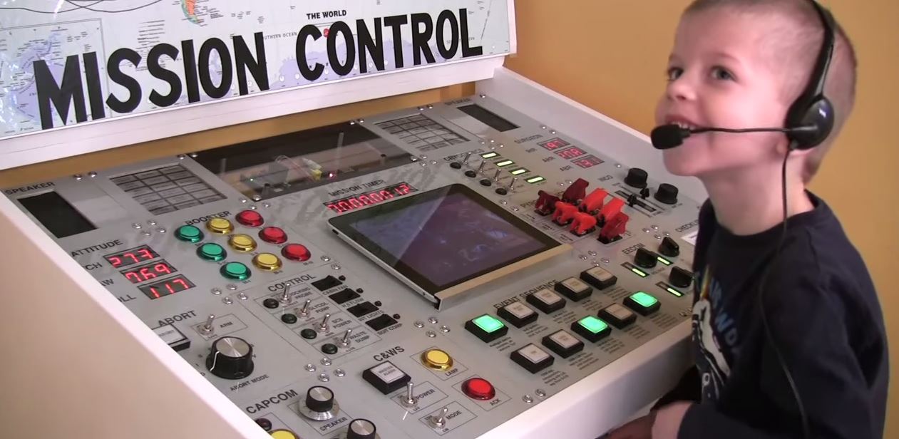
Both my boys and I still had space travel on our minds from our summer trip to Kennedy Space Center. For this desk project, I decided to go with a NASA theme. I researched the Apollo Program as well as NASA’s Mission Control Center, and designed my own console roughly based on those. I say “roughly” because the actual Mission Control does more monitoring than controlling, and isn’t awash in the whiz-bang rocket noises young kids appreciate.

I took great liberties and made more of a “space-themed” play console than an accurate simulator. My goal was simply to provide some extra ideas and sound effects for my two sons to play “Space” together.

The desk resides under my son’s loft bed (which I also built), and stays closed until the homework is finished:

Mission Control Desk Closed

When playtime begins, the lid flips up to reveal the Mission Control console:

Mission Control Desk Open

This is not an incredibly detailed guide giving all measurements and telling you which part goes where. Instead, I’ll give you step-by-step guidance regarding the major parts to aid you in your journey of learning and making.

Project Steps

Decide on scale

Figure out what your goals are for the project. How much time and money can you spend? Do you want to learn a lot of new things or stick to what you know? Do you want to lean more towards historical accuracy or whiz-bang playability? How much room do you have for the finished build? Would a smaller, briefcase-size control panel suit your play better, or would you like to build a hidden control panel into a wall, hidden behind a swing-away picture?

Obviously, a desk-style console is truer to NASA’s Mission Control than a hidden panel, but part of the reason for making things yourself is to make them the way you want them. Don’t get caught up worrying about an accurate reproduction, just make it fun.

Design control panel

The size of the desk will depend on what you want your control panel to include. Think about what you’ll do for displays, speakers, and controls. I chose many different types of LED displays, and used an iPad mounted in the console for complicated displays (such as velocity graphs) and learning about space through online research and videos. I used a decent set of computer speakers for sound. The speakers were the right size for mounting in my panel and the subwoofer fit nicely under the desk.

Design each of the individual panels, as well as the master layout. It’s important to know exactly what controls you’ll have so you can order parts and then cut out the appropriate holes. If you don’t trust the datasheets or don’t know how to mount something, you might need to order it first and then design the panel around it once you have it in hand.

Labels

I researched and tried a few different labeling techniques before deciding on the inkjet transparency method. There are more professional ways of labeling, but I chose the one that got me a look I was happy with for a price I could handle. I could have saved money by either using a handheld label printer or by hand-stenciling them, and I could have made them nicer looking by using silkscreens, a CNC engraver, or having them laser-etched in aluminum. Pick the balance that works for you.

For the transparency method, be mindful of how you’ll treat the edges of the labels. I actually restricted the size of my individual panels to make sure most panels would fit under a single label sheet. My Sequence and iPad/Mission Timer panels are too big for an 11-inch wide label, but I have plans to run a piece of trim over those edges soon.

When printing transparencies, less ink is better. I went into the advanced settings on my print dialog box and turned the ink usage all the way down, and still ended up with a cracked, desert-floor look to my labels. I had to adjust the transparency down to 98% in my drawing application to get the labels just right. I printed the labels mirrored so that I could glue them ink-down for longevity.

Individual panel layout

After you’ve decided what you’re going to put in each panel and how you’re going to label the panels, use a drawing program to lay out the individual panels. Even if you don’t intend to use transparencies for labeling, having printed templates for cutting out holes will ease the build process greatly. When placing the controls on the panel, watch out that you don’t put things too close together. Keep track of how big the controls are on both sides of the panel. Even though the toggle switches require just a 9/16″ hole for mounting, they have a chunky box behind the panel and can’t be placed too close. Other items, like the barograph LEDs, are small, but if you are soldering directly to them, leave enough room to get in to wrap and solder the wires.

Cutting out panels

Once the layouts of each panel are done, print them out backwards (mirror image) and glue them to the back of the panel blanks for cutting. By doing it this way, you don’t have to remove the template afterwards, it’s out of sight. If the panels are Masonite like mine, a razor knife, rasp, and file will serve to clean up any rough edges.

Prime and paint

Using a primer means that you won’t have to use as much of your colored paint to get full coverage, and that the colored paint has a better chance of being the color it shows on the can. When spraying, don’t start spraying, stop spraying, or change direction over the work. Start off one side and spray off the other side before releasing the nozzle. This will get you good coverage without spots and runs. It’s also better to do multiple thin coats than trying to do fewer heavy coats. Heavy coats of paint risk spots and runs and impart strange textures.

Populate control panels

This part is fun because you can start to get a real feel for how the finished product will play. Get everything in right-side up. Numerical displays won’t be as useful if the decimal points are on the top edge. Barograph displays don’t care, but do them all the same way (they’ll have a label or bobbed corner for reference) to make the wiring easier on you. Switches will work either way, as you can program things to come on when the switch is off, if necessary, but having some uniformity will expedite things.

Wiring switches

The basic design of the switch-reading mechanism is that the switch sits between the MCP23017 input pin and ground. The internal pull-up resistors of the MCP23017 are enabled. The Arduino keeps an array holding the previous state of each switch and runs a loop comparing the current state with the previous state.

If they differ, the Arduino sends a serial message to the Raspberry Pi telling it which switch changed state. Each switch has a number assigned to it. If the switch was closed (“turned on,” completing the circuit), the Arduino sends the switch number. If the switch was opened (“turned off,” breaking the circuit), the Arduino sends the sum of the switch number and 128. That way, the Pi can just check if the number is over 128 and then set an “off bit” and subtract 128 before processing the switch number. I found this more expedient than designing a more complicated protocol.

Before you build any control panels, breadboard out the switch reading bits, making sure you’re successfully reading switches with an MCP23017 connected to an Arduino. You don’t want to build and wire everything and then realize that you hooked it up wrong or that you have too steep of a learning curve with the programming. There are code libraries that make using the MCP23017 easier. I didn’t use them in my code because I thought I would need to use interrupts. I discovered that I was able to poll the inputs fast enough, though, and would use a library if I started again.

Wiring potentiometers

The potentiometers are connected to the Arduino’s analog inputs and are polled in the main loop. The value, which ranges between 0 and 1023, is mapped to the range of 1 to 12, and that number is passed to a function that lights up the appropriate number of segments on a barograph display, changing the color of all segments to denote the condition (red for way too little, yellow for too little, green for enough, yellow for too much, red for way too much).

Wiring LEDs

The idea of using an LED matrix driver scared me at first. I looked at using an Arduino Mega to get more outputs, but that wasn’t going to be nearly enough outputs.

I thought next that maybe I could use MCP23017 expanders for the LEDs as well as the switches, but each MCP23017 can only control 16 LEDs per chip, whereas the HT16K33 LED matrix driver can handle 128 LEDs per chip.

In short, if you order enough switches and LED displays from Adafruit that they send you a free Raspberry Pi, you are going to need LED matrix controllers to control them all. As with reading the switches, practice on a small scale with a breadboard first. You need to wrap your head around how an LED matrix is wired before you can make it do your bidding.

Design desk

After you’ve designed your control panel, it’s time to design a structure to hold it.

Be sure that the height is appropriate for your user and that all controls are reachable. Make sure the desk isn’t so thick that it sits too close to the lap and/or rises too close to the chest.

I used a sloped lid so I could put low profile controls toward the front and taller controls toward the back and present a relatively thin front edge. Allow space for wiring, clearance for the protruding switches under the closed lid, and a way to service the back of the control panel if a problem arises.

Consider the safety of the finished furniture, too. Provide a mechanism to hold the lid up once opened, or maybe use a “soft-close” mechanism. I left the front edge of the desk open for safety when closing (no pinch points where your hands are).

Build

For me, the design of the console took longer than the building, but the epic amount of soldering came close.

Sounds

You can find audio from the Apollo 11 mission at the Apollo 11 Flight Journal. Use Audacity for editing, if you don’t already have an editor. Make sure all your files are in 16-bit signed WAV format, and that the sampling rate matches what you’ve chosen for the pygame mixer in your code.

Programming

You can view my code on GitHub, and modify it to fit your needs or just read it to get ideas for what functions to use and how to structure your own code.

In order to run my simulated Apollo 12 lightning strike and Apollo 13 incident in the background while still responding to other switch changes, I used threading in the Python script on the Raspberry Pi.

You may have also noticed that I put a sleep delay between LED commands sent to the Arduino. When I send them too close together, commands get dropped. This is likely a bug in my Arduino’s serial receiving code.

I could have used an Arduino audio shield for playing sound, but I wanted the flexibility of the pygame mixer, as well as the speed and ease of changing the code on the Raspberry Pi. There also aren’t many solutions for playing multiple sounds at once with an Arduino, and I wanted to be able to trigger shorter sounds like thruster firing and pyrotechnic deployments while background-type noises like fans and pumps continue uninterrupted. One more big reason I chose to use the Pi was the limited memory of the Arduino. It can handle its current load fine, but would not have the space necessary to store complicated gameplay.

Play and refine

As you play, think about ways to improve the software and hardware. Maybe that means programming in some more advanced event sequences, maybe it means taking it as far as providing a full simulation of a mission, with a way to win and lose. Myself, I’m not going to refine with any winning or scoring in mind. Instead, I’ll be studying ways I can use the fun lights and noises to guide my boys to spark curiosity and prompt learning about space travel.