YouTube player

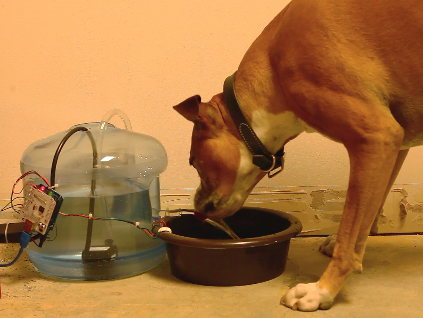
Here’s an automatic minder to keep your furry friends’ water supply topped up while you’re away or indisposed. Two homemade dip probes, connected to a microcontroller, sense the water level in a pet’s dish and automatically activate a pump to refill it from a reservoir when it gets low, or send a tweet when the reservoir runs out.

The system I built is based on an Arduino microcontroller, which reads two sensors and controls the waterworks. The simple dip probes are built from just a transistor connected to some wire. The reservoir can be any size but I chose a 3-gallon jug — it lasts a good while but it’s not too bulky. The pet water bowl is filled by a small aquarium pump that sits at the bottom of the reservoir.

The tweeting capabilities come from an Arduino Ethernet shield (or a WiFi shield if you want to get fancy). If the pet bowl doesn’t fill up after a set time in the code, due to an empty reservoir or a sensor failure, it will automatically shut off and post an error tweet, so you can hurry home and top off your pet’s tank.

wp12_pww02

Stella_Pet_Drink

Project Steps

Build the sensor circuit.

Build the water sensing circuit on a breadboard, following the schematic diagram and breadboard layout diagram shown here.

The circuit has 2 copper wire “dip” probes to detect high and low levels of water. A “base” probe (bare copper wire) at the bottom of the dog bowl forms a complete circuit when a probe touches the water, thus sensing the water level. Two LEDs reflect the status of the probes.

Test the sensor circuit on the breadboard before soldering it onto the MakerShield.

Put it on the MakerShield.

Solder your final sensor circuit on a MakerShield as shown here.

To indicate the state of the sensors via the Arduino, connect a pair of wires between the transistors’ collectors and the MakerShield’s contact pads for Arduino pins A1 (low dip probe) and A0 (high dip probe).

Measure the voltage at each transistor’s collector with the probe in the water (sensor “on”) and out of water (sensor “off”), and adjust these limits as needed in the Arduino code beginning on line 111, depending on the voltage values you measured for on and off. The collector is the pin connected to the LED’s cathode. (The anode will always read 5V as it’s connected to power.)

Attach sensors to the pet bowl.

Strip a few inches of insulation off the base sensor wire and attach it to the bottom of the pet bowl with some Sugru, so that a couple inches of exposed wire lie flat on the bottom.

Stick the low and high probes to the side of the dish with more Sugru. These need only a tiny bit of exposed wire. Keep them well clear of the base probe so there’s no chance of accidental contact.

Prepare the reservoir.

Cut the top off the 3-gallon jug to make an opening just big enough for the aquarium pump to fit through the top.

Connect the pump to the hose.

Fasten the pump to the bottom of the reservoir. Mine has suction cups and those seemed to work perfectly.

Drill a 1/8″ hole in the hose, somewhere near the top of its arc but still inside the reservoir. This little vent will break suction and prevent water from siphoning out after the pump switches off. Any water that dribbles out the vent during pumping will run back down into the reservoir.

Program the Arduino.

To send tweets from the Water Warden, you’ll need an OAuth token. While you’re at it, download and install the Tweet Library for Arduino.

Download the project code here. Open it in the Arduino IDE software, and paste your token where indicated (and if necessary, your network credentials). Then upload it to the Arduino board.

The code includes libraries for SPI (serial communication), Ethernet, and Twitter, so the Arduino can easily communicate. It defaults to DHCP mode automatically, allowing your router to assign it an IP address.

Then it sets the Arduino’s pin 8 to control the PowerSwitch Tail, and goes ahead and sets up an Ethernet connection and starts checking on the status of the water sensors.

Connect it all up.

Solder the PowerSwitch Tail to the Ethernet shield as shown here: connect a wire between the PowerSwitch Tail’s In(–) terminal and the Arduino’s ground, and another wire between the In(+) terminal and Arduino pin 8.

Plug the MakerShield into the Arduino, then plug the Ethernet shield into the MakerShield.

Plug your aquarium pump into the PowerSwitch Tail. Run the hose into the pet bowl.

Double-check all probe and pump connections to the Arduino. Finally, with everything connected and the program loaded up, connect the 9V battery pack to the Arduino.

Use it.

Now you should have a self-sufficient dog hydrator! For as long as the reservoir lasts.

The program continually checks the dog bowl for water every 10 seconds.

The Arduino fills the dog bowl until the high dip sensor is active, indicating the bowl is full.

Tweak it.

When the Arduino starts filling the bowl, it also starts a timer. If the bowl isn’t full within 45 seconds, it assumes the reservoir is empty and sends a tweet to your account letting you know that your dog might dehydrate! (You can tweak this timer interval depending on the size of your pet’s bowl.) Then a fail-safe routine exits the program entirely, so that it won’t pump again until you come home and reset it. (This ensures that in the event of a bad sensor or other error, the system will shut down instead of pumping water on your floor.)

You can also change the delay(10000); to check the water more frequently than every 10 seconds, but the longer interval helps prevent oxidation on the wires because the wires underwater are energized much less often.

Make it wireless (optional).

If using an Ethernet cable to your router is impractical, you can make a wireless Pet Water Warden by substituting an Arduino WiFi Shield for the Ethernet Shield. This requires running a different program on the Arduino to handle WiFi communications — download it here.

The wireless version of the code works by using taking advantage of two libraries: the Twitter library and a modified Ethernet library tailored for the WiFi shield.

Explore the Arduino code.

The sketch setup begins by setting the pump to “off” to avoid any accidents. Then the presence of the WiFi or Ethernet shield is detected. For the WiFi version the program attempts to connect to the desired SSID and password with automatic DHCP. You can also enter manually your preferred network settings if desired.

After the internet connection is confirmed, the Twitter account is tested to make sure tweets can be made. The results will be posted in the serial monitor.

The main program begins by reading the analog pins on the Arduino for the high and low probe sensors. The value is then converted to a voltage between 0 and 5V to be used to determine whether or not the sensor is on. I used a hysteresis where anything above 3.5V is on and anything below is off; open the Serial Monitor console to see what voltage values your probes are giving. You may need to adjust the ranges depending on the amount of water your bowl holds, how close you placed the sensors, and your water quality (for example, purified water is less conductive than mineral-rich water). If there’s no water touching the high probe and the pump is off, the code turns the pump on and starts a timer. If the bowl doesn’t fill up in about 45 seconds (an interval that can be changed in the code), the program will assume either that there’s no water left in the reservoir or that something went wrong while filling up the bowl, and will then turn the pump off and post a tweet about the error. Then the failsafe exit();function quits the program entirely until you reset it.

The main loop runs only every 10 seconds, to help slow the oxidation of the wire probes, but this interval can be changed in the code.

You can also change which pin the pump is connected to (it’s currently pin 8). But note that pin 7 cannot be used with the WiFi version because that’s used as a handshake between the WiFi shield and the Arduino. The analog input pins used are A0 and A1, and these can also be changed. And of course the tweet message can be edited too.