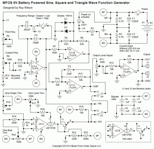
This is the conclusion to my last article, “Make a 9V Battery-Powered Function Generator.” The schematic and the circuit description were presented in that article. In this article, I present some construction tips and drawings to help you actually build and use the circuit.
PC Boards
As I mentioned in the last article, you’ll need a case to put the battery signal generator in and a faceplate to hold the front panel controls. I’m no case guru, so I’m leaving the case construction to you. Buy a Radio Shack case, or maybe a Hammond case, a BUD box, a cardboard box, or a nice wooden box you make in your shop. As long as the front plate can hold the controls, you should be fine. I prefer conductive material for faceplates because it grounds all of the pot bodies and reduces noise in the system. Run a ground wire from the faceplate to the circuit’s ground for best results. I’ll show you where in the following information.
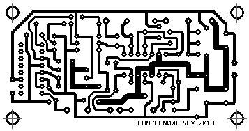
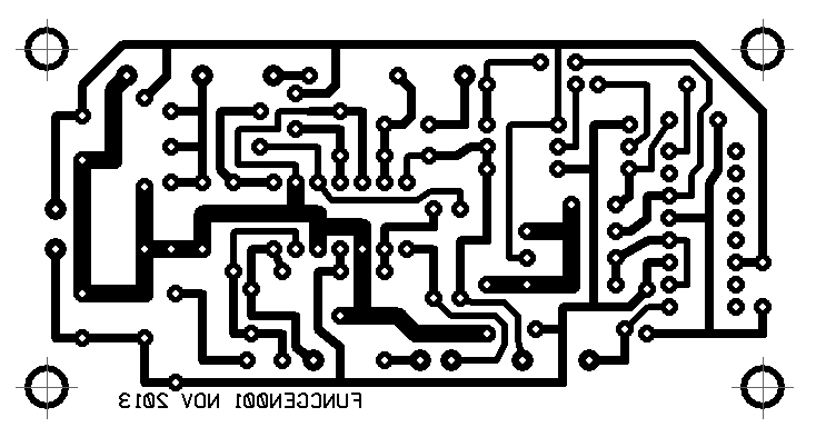
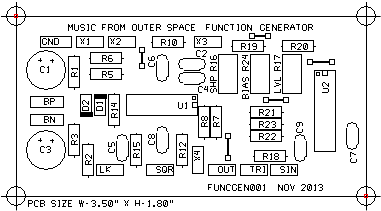
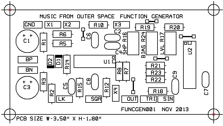
Although I sell double-sided PC boards for my projects (including this one at MFOS) I know it is easier for hobbyists at home to make single-sided PC boards. The following board layout is sized for 1 to 1 contact artwork. If the art does not print so that you have 1/10″ between adjacent IC pads and 3/10″ between IC pads across from one another, try adjusting the pixels/inch of your art program until it does. I’m not an art program expert and the patterns print correctly for me on my laser printer so I wish I could give more help there but . . . I can’t. I’ve included a 2X pattern as well in case it comes in handy. The component legend silk screen pattern is there for the die-hard home screen printers. I know how it is. I used to do it. A word to the wise: be careful with the chemicals involved in the board making and screening processes. Wear gloves and goggles, have good ventilation, and dispose of things properly. You’ll be glad you did.
Single-Sided PC Board Info (For home hobbyists who make PC boards)
Single-Sided PCB Bottom Copper (as viewed from the bottom of the PC board)
Single-Sided PCB Legend Silk Screen (as viewed from the top of the PC board)
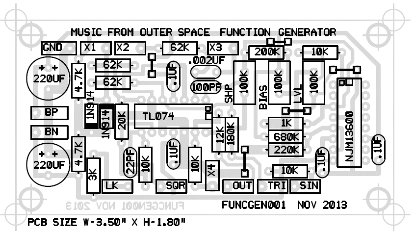
Here is a view of the values that go at each of the legend locations on the PC board. This view is handy for the board population stage. You won’t need to refer back and forth to the schematic while inserting components—just use this chart. Double check that you’ve put a resistor or capacitor in every location or you’ll be trouble-shooting later. Make sure you solder every solder joint as well or, you guessed it, trouble-shooting again. I’ve highlighted the fact that you must install a wire jumper in the four locations inidacted on the PC board. This is normally a piece of 22 to 24 gauge solid copper wire bent to fit the holes. Trimmed off resistor leads often work well.
You must insert wire jumpers where indicated for the single-sided PC board.
Single-Sided PCB Showing Component Values
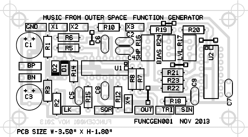
This view is handy for the project trouble-shooting stage. You can refer to the schematic and then easily find any component by its designator. Working your way through the circuit requires that you be able to locate all of the electronic components shown in the schematic. This is your map to know which is which.
Single-Sided PCB Showing Component Designators
Front Panel Layout and Wiring
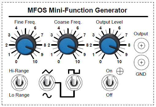
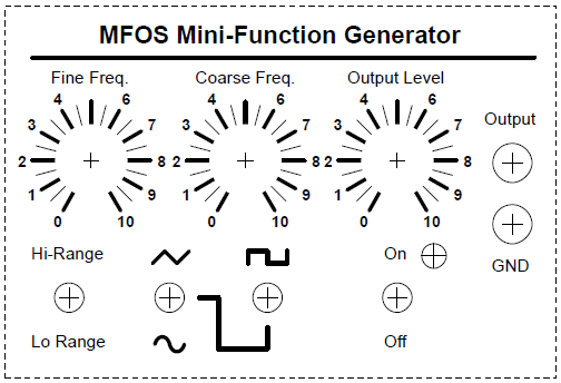
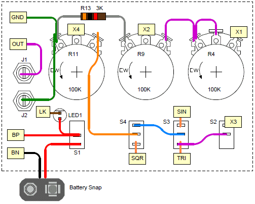
I show three views of the front panel below. The conceptual view shows the panel with its controls. The mechanical view is used as a hole pattern. You lay it over the material you plan to use for your front panel and then use a center punch to make drill guide divots. The wiring view shows both the interconnections for the panel controls and the points on the front panel that connect to the PC board. The “Xn” designators on the PC board are external connection points.
Conceptual View
Its always a good idea to think about your front panel and to make a mock-up drawing so that you don’t forget a control you may want and so you can arrange the panel logically. You can cut and paste using any art program to come up with a conceptual drawing for your control panels.
Mechanical View For Fabrication
Print a copy of this for use as a drill hole guide. I like to tape mine squarely to the material I’m using for the front plate and then use a sharp center punch to make drill guides at every place I plan to drill a hole. Be sure to use the correct drill size for the components you mount. The potentiometers and banana jacks usually fit in 5/16″ holes; the mini-toggle switches normally fit in 1/4″ holes. Size the LED’s mounting hole for the type you buy. The regular-sized ones (good old fashioned LEDs) are typically 0.2″ (5mm) in diameter.
Wiring View
I find that 22 to 24 AWG size stranded wire works well for panel wiring. First, solder the wires (or flying components) that run between panel components. Next, wire each labeled PC board port (donut pad with an Xn label near it) to the corresponding Xn point on the front panel diagram as indicated. This is where 90% of the trouble-shooting issues are born, so check your wiring carefully—and then check it again.
Putting it All Together
Gather all required components for the project.
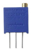
I suggest you shop online unless you have a local component store with good selection and pricing. Just search for electronic components and you’ll find hundreds of online retailers. Shop around, as prices can vary widely. Use 1/4 watt resistors and capacitors with at least 25V ratings and 5mm (0.2″) lead spacing. Use trimmers that are physically similar to BOURNS 3296W style. They look like this and are sold at Tayda.
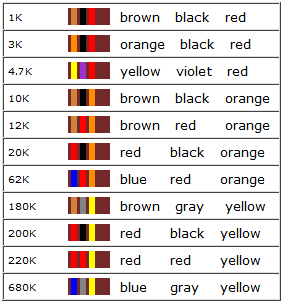
Resistor Color Chart For Resistors Used In This Project
Possible Capacitor Markings
Capacitors come marked in several ways. The capacitors that are used in this project may be marked as follows:
| Value | Possible Marking 1 | Possible Marking 2 |
| .002uF | 202 | 2nF |
| .1uF | 104 | 100nF |
| 100pF | 101 | |
| 22pF | 220 | |
| 220uF |
Populate the PC Board
Populate the PC board, inserting and soldering lower-profile components before higher-profile components. For example, begin with wire jumpers, then resistors, then IC sockets, finally any remaining components.
Print Faceplate Template
Print the faceplate template and use it as a model to fabricate a faceplate. Fabricating the faceplate can be done using 1/16″ sheet aluminum or other material, but I recommend conductive material. Using one of those project boxes that come with an aluminum faceplate should work perfectly.
Populate Panel
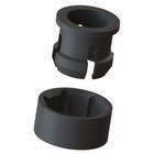
Insert the panel components onto the faceplate (pots, switches, LED, banana jacks). Align them the way the wiring diagram shows and make sure to tighten the mounting nuts. Some crazy glue can be used to mount the LED in its hole or you can purchase a plastic LED clip-n-ring set with which to mount the LED. The LED clip-n-ring style holder looks like this.
The clip inserts into the LED’s hole from the front of the panel, the LED is inserted into the clip from behind the panel. Finally the ring is snapped over the part of the ring sticking through the back of the panel which locks the LED in place. Drill the LED’s mounting hole keeping the size of the particular LED and clip-n-ring set you buy in mind.
Wire Front Panel
Wire the front panel components together as shown in the wiring diagram. Carefully check your work, as most mistakes happen in panel wiring. It is a good idea to print out the panel wiring diagram and check off the wires in the diagram as you install and solder them. For connections that will also connect to the PC board, it is a good idea to temporarily tack-solder the wire to the terminal, leaving room for the wire that will also run to the PCB. Then, when installing the panel to PCB wires, apply more solder to the tacked connections to make them secure.
Wire Panel to PC Board
Wire the circuit points marked on the front panel diagram to the corresponding circuit points on the PC board using stranded 22 to 24 AWG hook up wire. Try to keep the wiring as neat as possible and use care while soldering. Shiny joints earn you points—I just made that up.
Turn Power Switch Off – Attach Battery
Insert a battery into the battery snap making sure to observe polarity. Even touching the battery terminals to the battery snap in the incorrect polarity can play havoc with your circuit if the power is on. Always have the power switch off when attaching the battery.
Turn Power On
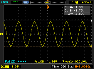
Turn the power on and monitor the output with an amplifier or oscilloscope. You should see the triangle and square waves as soon as you power the unit. They should be about 3 to 3.5 volts peak-to-peak when the output level is turned fully clockwise. You can use the output level pot to adjust the level as needed for use. You will need to adjust the sine wave trim pots in order to obtain a nice low distortion sine wave.
Sine Wave Adjustment
- Adjust 100K trim pot R16 so that the top and bottom of the sine waveform have the typical sinusoidal curve. You don’t want the wave to appear too flattened at the top or the bottom too triangular. Adjust R16 until the sine wave looks as sinusoidal as possible.
- Use 100K trim pot R24 to adjust the top-to-bottom symmetry of the sine wave-shape.
- Use 100K trim pot R17 to adjust the amplitude of the sine wave-shape to about 3.5V peak-to-peak.
After trimming, your sine wave should look like this:
Trouble-Shoot as Necessary
Any time you turn on your project and it works the first time, give yourself a nice pat on the back. Otherwise, you have some trouble-shooting to do. Panel wiring is often a source of errors, but there are a myriad of possible causes. Here are some tips I’ve put together over the years because, as you can imagine, I have done my fair share of trouble-shooting. Trouble-Shooting Tips…
I hope you enjoy building this project and that it gives you years of service. As always . . . keep imagining, keep inventing, and stay ingenious!
Ray Wilson is the author of Make: Analog Synthesizers and the genius behind the very popular Music from Outer Space website.
ADVERTISEMENT


