Cover of Make: 94 - Fantastic Realms
This article appeared in Make: Vol 94. Subscribe for more great projects.

Cuckoo clocks had their heyday in the second half of the 19th century. In the 1850s, the Black Forest area of Germany produced 600,000 clocks each year, increasing to approximately 1.6 million units in 1880. The cuckoo clock became known and appreciated not only in Europe, but worldwide. Its reputation as a symbol of German craftsmanship and tradition was cemented during this time, and continues to this day.

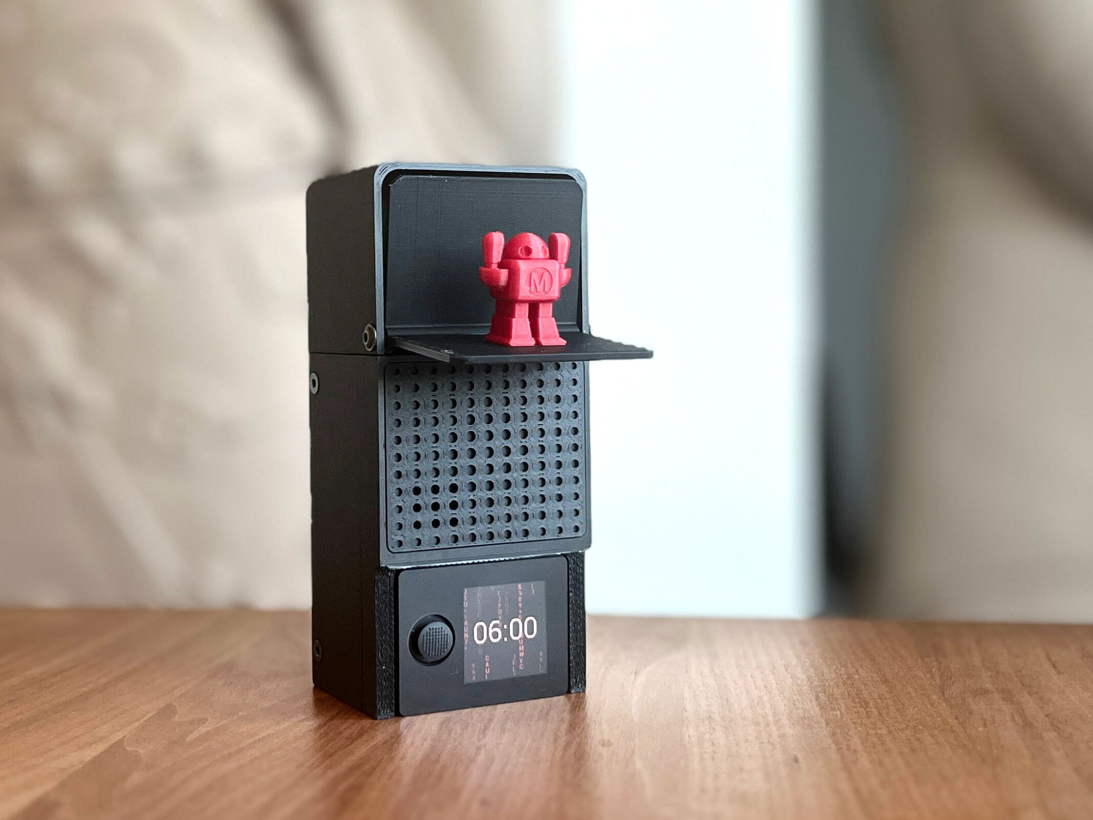
Our version also has some mechanics in it, but of course never comes close to these sophisticated mechanical works of art. Our clock is equipped with an Oxocard Connect, with time synchronized via the internet, and a somewhat oversized 64-voice synthesizer for background music. And Makey takes the place of the cuckoo and gives us a big hurrah every hour on the hour!

Project Steps

Structure

This slideshow requires JavaScript.

Our model consists of just a few plastic parts, for which we have provided the STL files. We use a micro servo, as supplied in the Oxocard Connect Innovator Kit, to move the flap; (Figure A); these are available from various suppliers. In order to produce something more than just simple beeps, we decided to use our new Synthesizer cartridge. Version 2 has unused pins available, which we will solder our servo and a USB cable to.

The Oxocard Connect is not permanently installed, but simply plugged in, so we can reuse it in other projects (Figure B).

3D-Printed Parts

This slideshow requires JavaScript.

We need five 3D parts for our model (Figuresand D); with the exception of the cover and the Makey robot, we recommend printing with supports everywhere. In Figure C you can see the optimal positioning, which requires the least material and delivers good printing results. You can print with 0.2mm layer height or 0.1mm, but the latter takes about half a day on a Prusa MK4.

Mechanics and Electronics

We use an inexpensive SG92R servo for the mechatronic part; one of these is included in the Oxocard Innovator Kit. The servo horn is connected to the flap with a 12mm length of wire.

The Synthesizer cartridge provides the acoustic background music. Version 2 has pins led out where we can solder our servo.

Six M3 screws are required for assembly. The length can be between 8mm–10mm. Four of them should have a countersunk head, two of them a pan head.

We will use an old USB cable for the power supply.

Assembly — Electronics

This slideshow requires JavaScript.

First find an old USB cable; I still have a lot of USB-A to micro-USB plugs in my treasure chest. Simply cut off one end and you can then use the other for another project. Remove the sheathing so that you can access the individual data and power wires (Figure E). We only need the black and red wires; trim and insulate the others to prevent short circuits.

Before we start soldering, we also cut the connector off the servo. Strip 3mm–4mm of insulation off all the wires, i.e. the three servo wires and the two USB power wires, and tin the ends with solder.

Now solder the wire connections (Figure F) as follows. Note that servo brown and USB black are soldered to the same ground pin:

Plug the USB cable into a power source; if you now plug the cartridge into the Oxocard Connect, it should turn on.

Install the Servo

This slideshow requires JavaScript.

The servo horn is extended with a piece of bare wire. Cut a wire 12mm–14mm long, heat it, and use pliers to attach it to the servo arm as shown in Figure G. If no wire is available, you can attach a 12mm countersunk screw with hot glue or super glue.

Before we can install the servo, we first need to position it. The Cuckoo Setup script (Figure H) helps us to do this. The flap can be opened and closed with up/down presses on the joystick.

Attach the servo with the servo horn so that it points downward, as in Figure I. Then use the joystick on the Oxocard to check whether the arm moves correctly.

This slideshow requires JavaScript.

Now carefully slide the flap over the wire and fix it in place (Figure J) with the two pan-head screws. The suspension of the flap is deliberately larger than 3mm. The screws are only used to hold it in position. It must remain freely movable.

Again, use the joystick to move the flap. If everything works, the last step is to fix the servo horn with the enclosed screw (Figure K). If the positioning ring is still not optimal, the servo horn must be removed and refitted.

Now we can align the Synthesizer cartridge. You can see in Figure L how the cables are arranged. The USB cable is led out under the circuit board to the left.

This slideshow requires JavaScript.

Slide the cover onto the circuit board from the front and then press it down. You can see in Figures M and N that there must be no cable under the cross-bar. When the two studs snap into place, the housing is plugged together and can then be fastened at the side with the four M3 countersunk screws.

TIP: If you open the housing again later, you can fix any loose studs with a blob of super glue.

Finally, apply the decorative grille (Figure O). Alignment is important here. Four of the holes are open all the way through; these should be positioned above the speaker, which is located at the bottom left of the circuit board. The plastic grille can then be attached with a little glue.

Software — Preparation

This slideshow requires JavaScript.

As the Oxocard is now offset by 90°, the screen content must be rotated. The function for this can be found in the Settings (Figure P).

Next we need to load a library so that we can use the synthesizer (Figure Q). We start the Setup script, which is found in the NanoPy editor (editor.nanopy.io) under Examples –> Cartridges.

Control Servo With PWM

Figure R. Definition of the initServo, openLid, and closeLid functions.

In our first script, Cuckoo Setup, we’ve already seen the code that shows how a servo can be moved in NanoPy (Figure R). A pulse-width modulation (PWM) signal is generated for this purpose. This is a current pulse at a specific interval; the frequency and the on-off duration of the signal tell the servo what position to move to.

Trial and error has shown that 35° opens the flap optimally and –80° closes it. This angle information is converted into a PWM value between 102 and 512 in lines 9 and 13. We then use the writePWM command to send the pulse to the servo pin. Learn more about PWM functions in the NanoPy References under IO Functions.

Internet Time

This slideshow requires JavaScript.

In order to make a clock, we need the time. The Oxocard Connect has an internal clock that sets itself automatically as soon as an internet connection is established. It can also be set manually using the setTime function. Internet time is provided in a general, time zone-neutral format. To use it, we must inform the system of our time zone. The Cuckoo Time script shown in Figure S sets the time zone to Europe/Zurich and displays the time on the screen (Figure T).

Line 1-2:
Here you can see how to set the time zone. The very cryptic codes are international standards. There is a list where you can find your code.

Lines 4-17:
We have a loop here that is called once every second.

Lines 7-8:
First, we get the hour and the minute and save them in a variable.

Lines 9-14:
There are no formatting functions for time in NanoPy. We have therefore briefly programmed these ourselves here. If the hour or minute is less than 10, we add a “0” in front of it. The two numbers are then joined together with a “:“.

Lines 15-16:
drawTextCentered” displays the time vertically and horizontally centered on the screen.

Music and Sounds

This slideshow requires JavaScript.

The SAM2695 chip used in our Synthesizer cartridge, from French manufacturer Dream, is a 64-voice stereo synthesizer with approximately 150 instruments/drums. There are also various effects, including reverb and echo, which can be used to manipulate the sounds. Some of the functions are explained in the NanoPy environment under Cartridges/Synthesizer (Figure U). It is worth working through the tutorial here first.

First, start the script Cuckoo Setup.

Next, the script Cuckoo Sound shows the basic structure and summarizes the parts we need for our project. When you start this script (Figure V), you first hear a violin, then a telephone ringing. Then we have a triad chord, where we play three notes at the same time, as an example of our polyphonic capabilities.

Line 1:
The synthesizer library is loaded here. This was previously loaded when the script “Setup” is installed. If an error occurs, the setup must be run again.

Line 3:
We set the volume. This is a value between 0 and 127.

Line 4:
There are channels in the MIDI music world. In ours there are 16, with channel 10 (number 9) being the drum channel. Each channel can have its own effects and instruments.

Line 7:
We have two commands on one line here. The first command selects the instrument set, the second sets the instrument. There is a list of the different instruments in the supplement, each with two numbers behind it. The first number is the instrument number, the second is the set. So if I want to play instrument 125 (telephone) of set 0, I enter the information as shown on this line. You have to subtract another number from the instrument. The standard MIDI instruments start with the number 1, but in computer science everything starts with the number 0, so you have to “add” -1.

Line 8:
We will now play a note. This is done using the noteOn command, which has two parameters. The first parameter corresponds to the note (0-127), the second to the velocity, i.e. the hardness of the note (0-127). If you do not know the number of a note, you can also use notetoNum here. This function expects a description of the note as text. C4 corresponds to the note C of the fourth octave.

Line 10:
Each note is played indefinitely. With noteOff in the same channel and the same note, this is switched off.

Lines 19-22:
We are producing a triad here.

Digital Rain — Animation

This slideshow requires JavaScript.

There is also a little bonus. The script Cuckoo Digital Rain shows the well-known animation from The Matrix film series (Figure W). For our Makey version we have switched it to red (Figure X) via the constant editor.

All Together

This slideshow requires JavaScript.

The complete clock script Cuckoo Version 1 combines the digital rain animation with the clock; Makey appears on the hour, accompanied by a beautiful triad tone. You can also click the button to trigger this at any time.

To ensure that this script starts every time the Oxocard is inserted into the device, it must be transferred to the cartridge. This is done via the context menu on the script (“Load on Cartridge”) (Figure Y). Now you can unplug the Oxocard and whenever you plug it back in, it will start Cuckoo Version 1 immediately (Figure Z).

Going Further

There you have it! We have developed a modern form of the cuckoo clock that has a lot of potential for your own experiments. You can of course replace Makey with other figures or even complete scenes, or illuminate the whole thing with an RGB LED. The Synthesizer cartridge also has other free pins to which you can connect other things. Thanks to the synthesizer, it is possible to, for example, bring birdsong into your home. Let us know what you make!

Photography by Thomas Garaio

This article appeared in Make: Volume 94.