3DPClock-4

If there’s one thing none of us have enough of, it’s time. Tracking the time we do have has been a goal of many great inventors — and building your own clock is practically a rite of passage as a Maker.

By the 1300s, we were creating accurate mechanical clocks with the invention of the escapement. But even the best pendulum clock would lose time aboard a rocking ship, rendering it useless for navigation. In 1714 the British government offered a reward to anyone who could devise an accurate shipboard clock, and in 1761 John Harrison’s Marine Chronometer finally met the test — over the course of 10 weeks it was only off by 5 seconds.

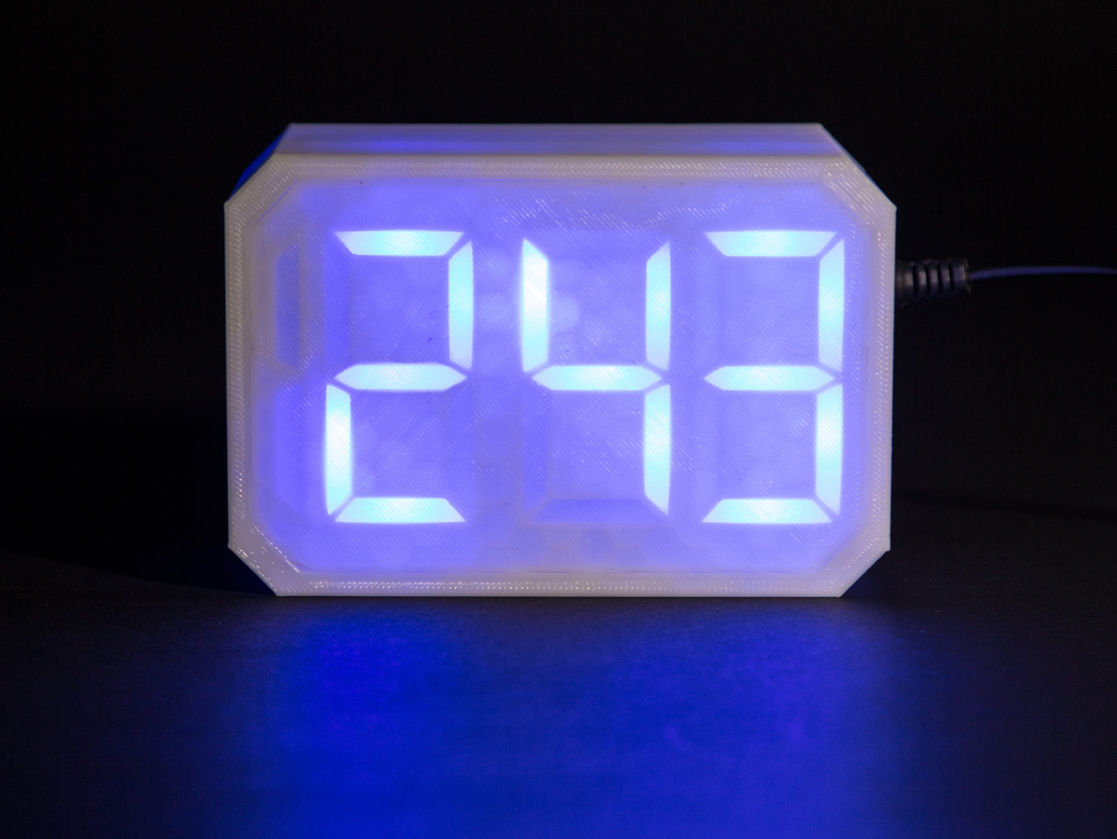
The first electric clock was patented in 1840 and the first quartz-timed clock built in 1927. Advances in solid-state electronics in the 1980s made it possible for quartz clocks to spread throughout the world. Mechanical clocks live on as decorative or luxury time pieces (a Rolex still has gears), but the humble seven-segment LED clock is now everywhere: your car, your cable box, your microwave.

In honor of the world-conquering LED clock, I’ll show you how to use a 3D printer to build your own jumbo-sized seven-segment LED desktop clock. It glows beautifully from within, and it’s even more enjoyable when you tell your friends you made it yourself.

Project Steps

Prepare the 3D parts

I started this project by designing the three printed parts in SketchUp: the case, the LED holder, and the digits block (the display face). Printing the parts takes about a day on most desktop 3D printers.

I drew the digits to resemble a standard seven-segment display. The thin front of the display diffuses the light from the LED within, causing the entire segment to glow. You could redesign the segments for a different look, but be sure to leave plenty of space between each segment to help reduce the bleed between them. The segments are sized to be large enough for the LEDs to fit into them but still hold them in place.

Test-fit your LEDs into their holes in the holder. If they won’t go in, use sandpaper or a knife to carefully enlarge the holes. You want them to be in there tight, so don’t go overboard.

Solder the LED chains

Hold an LED with its leads pointing straight up, the longer lead toward you and the shorter lead away from you. Bend the short (negative) lead of your LED over 90° to the left, near the base of the LED. Do this to all 23 of your LEDs.

Now get your soldering iron fired up. Take 2 of your prepared LEDs, and solder the tip of one of the bent leads to the corner bend of the other. Take a third LED and solder its corner bend to the unsoldered negative tip of the previous pair. Continue doing this until you have a chain of seven LEDs.

Make 2 more chains like this.

Install the LEDs

Place the 3D printed LED holder on top of the digits block, with the “8s” to the left and the “1” to the right. Now insert an LED chain into the leftmost “8,” starting with the top leftmost hole, so that the chain forms a backward S shape. Do the same to your other two “8s” with your other two LED chains.

Place your last two LEDs into the last 2 holes for the “1” digit. Turn the bent leads toward each other and twist them together leaving a 1/8″ (3mm) tail sticking up, and then solder the wires together.

Clip all of the long (positive) leads from your LEDs down to about 1/8″ (3mm).

Populate the proto shield

Now let’s start prepping our prototyping shield. Start by soldering on the header pins. I find the easiest way to do this is to first insert them into my Arduino, then set the proto board on them. This way even if the headers on your Arduino aren’t perfectly straight, your shield will be matched to the Arduino.

Remove the proto shield from the Arduino. On the shield, place the seven 220Ω resistors into the holes corresponding to digital I/O pins 6 through 12, then place their opposite ends into a straight row of holes in the “blank space” on the shield. Do the same for the 4.7K resistors in holes 2 through 5, but this time leave a bit of space for the transistors (at least 1 column and 3–4 rows) as shown. Ensure that none of the resistor leads are touching each other.

With the flat side of the transistors facing toward you, insert them in the board one row below the 4.7K resistors, with their center pins aligned with the resistor lead. Solder them in place.

Connect the cables

Cut 8″ of ribbon cable and remove any extra wires so you’re left with only 8 wires. On one end of the cable, cut 1½” off 7 of the leads, leaving just one long wire. Separate all these wires by about ½” and strip them all about 1/8″. On the other end of the cable, separate all the wires by about 1″ and strip them all.

Starting with the short wire furthest away from the long tail, solder it into the hole below the resistor for pin 12. Work across all of the short wires for pins 12–6. Solder the long wire into the proto board to correspond to the left pin of the transistor that’s hooked up to pin 2 of your Arduino. As you solder these wires in place, create solder bridges that connect them to their appropriate leads above.

Connect the cables (cont'd)

Prep 2 more cables identical to the first, and solder them directly below, again connecting to pins 12–6, and to the left pins of the transistors for pin 3 and 4, in that order.

Prep a final cable in the same fashion, but instead of having 8 wires, this one should only have 3. Solder it into pins 8 and 7, and then into the left pin of the final transistor hooked to pin 5.

Finally, cut 4 lengths of hookup wire long enough to stretch from the right pins of the transistors to a place on the board where you can bring them all to ground.

Connect the LEDs

Before soldering, slip a length of heat-shrink tubing over each wire in your cables.

Starting with the topmost cable on the shield and the leftmost “8” digit in your pattern of LEDs, solder the cable to the now short and yet unsoldered LED leads using the guide here. Solder the remaining wire (from the pin 2 transistor) is to the remaining tail of the LED chain.

Connect the 2 remaining 8-wire cables, moving from top to bottom, to the 2 remaining “8” digits, moving from left to right. For the final, 3-wire cable, connect its long (transistor) wire to the tail created by the 2 clipped leads tied together on the “1” digit, and connect its 2 short wires to the remaining 2 short leads from the 2 LEDs.

With that, your soldering is done!

Upload the Arduino code

Install the 2 included libraries into your Arduino environment. If you’ve never done this before, follow this guide. These libraries make it easy for you to keep track of time and to work with seven-segment displays like the one you just finished building.

Now plug your proto shield and a USB cable into your Arduino, and your Arduino into your computer. If you’ve never used this particular Arduino before, you might need to install some drivers before you can proceed. If this is a problem consult arduino.cc for help.

With your Arduino plugged into your computer, open ThreeDPClock.ino in the Arduino IDE. On the Tools→Board menu, select the Arduino you’re using, and on Tools→Port select the appropriate serial Port. Then hit the Upload button to load the code onto your Arduino.

Set the time

Sadly, computers are not great at dealing with dates we understand; they work better on their own date/time routines. To set the time and date on your clock, you need to set the epoch time (aka Unix timestamp) on your Arduino. Go to this website and use the dropdown menus to set your desired time, then hit the “Human date to Timestamp” button. Copy the “Epoch timestamp” that’s created.

In the Arduino IDE, immediately open the Serial Terminal and set the data rate to 9600. You should be prompted to set the time now. Type in “T” followed by the epoch timestamp you copied (for example, T1425320521). Hit Enter and your time should now be set. Take a look at your clock and see if it’s telling time as you think it should.

Put it all together

Slide the LED assembly into the case, backside first. If it’s too tight, you can carefully sand the inside of the case but make sure not to overdo it — you want these parts to fit neatly by friction so you have a nice seamless case. That’s it!

Conclusion

Now your clock is assembled and ready for enjoyment. Place it on your mantel or your desk and use a wall power supply to keep it running. You’ll still need to set the time via USB but once you plug in the wall supply, the clock will keep running after you unplug the USB.