featured

3D Printing Projects
This project is one of the eight new builds found in Make: 3D Printing Projects, a new compilation title led by Printrbot’s Brook Drumm.

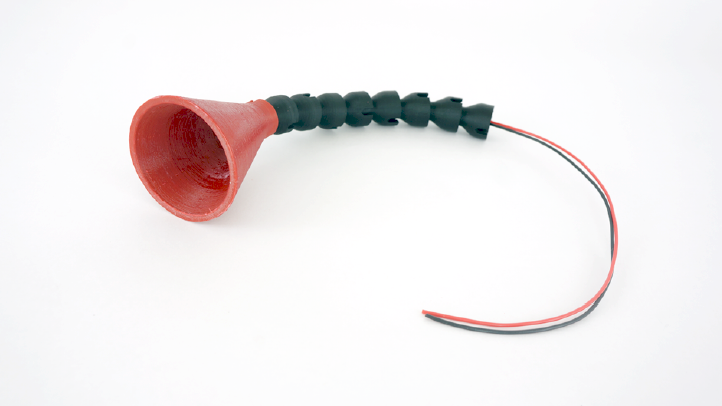
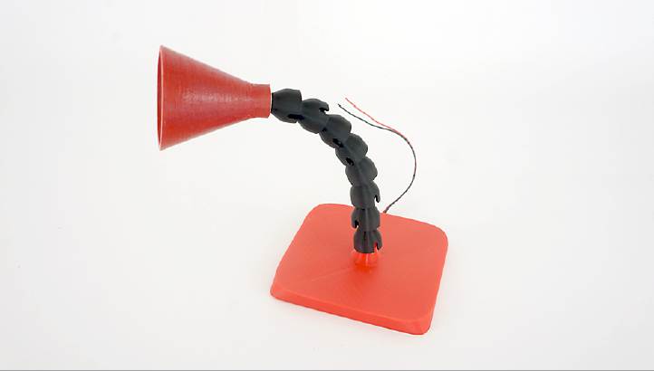
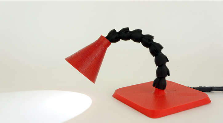
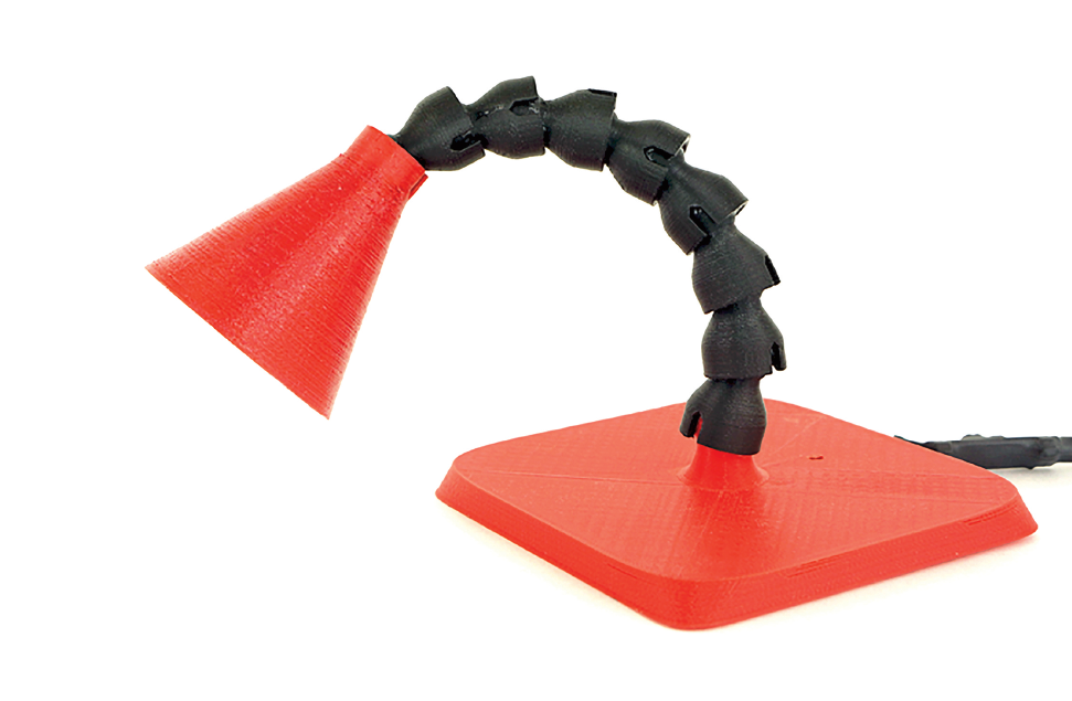
Lamp3D is a small, repositionable, gooseneck-style LED lamp. It’s a fun and easy introductory project for those just starting out with 3D printing, electronics, and soldering.

The minimalistic design of this lamp was inspired by the Loc-Line modular hose/pipe system that’s been used for everything from CNC machine lubrication to flexible shower heads. All of the lamp’s structural components are 3D printed, with no additional hardware required.

It can be easily customized by adding more linkages (or “vertebrae”) or by modifying the lampshade. Plus, we can fabricate it on a very small print bed.

Be sure to get your tools, materials, and files sorted before embarking on this fun project.  All the files and code for each of the projects in the book is available from the Make: 3D Printing Projects GitHub site.


Here are the 3D printable files you’ll need to get started:

Quantity           Description                    Filename

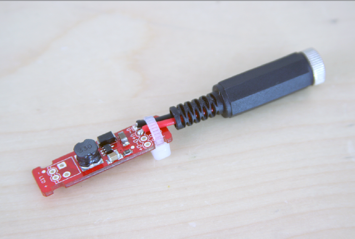
1                      Lamp Base (ABS or PLA)      Base.stl

1                      Lamp shade (ABS)                 LampShade.stl

9+                   Vertebrae (ABS)                    Vertebrae.stl

Project Steps

Print Your Parts!

Print out all the files: one base, nine or more vertebrae, and one lampshade. I recommend printing these parts in ABS at 100% infill. PLA is less flexible and could snap when it comes time to put the pieces together. While your printer is cranking out the plastic bits, it’s time to get started on the lamp’s electronics!

Wiring the Barrel Jack

Cut two 2″ sections from each color of our hookup wire (one black and one red).

Strip about 1/4″ of insulation from each end. Unscrew the black housing on the barrel jack and solder the red wire to the center and the black to the outer leg. Then slide the 1/4″ of heat shrink tubing around the red wire connection to insulate it.

Use a pair of needle-nose pliers to close the collar around the wires, then screw the black housing back on.

Add the LED Driver to the Barrel Jack

Now it’s time to add the FemptoBuck LED driver to the wired barrel jack you’ve just created. Solder the black wire to PGND (marked on the board) and the red wire to VIN.

Take a zip tie, wrap it around the wires, and seat it in the notches on the sides of the FemptoBuck. This will provide strain relief for our solder joints.

Now set this assembly aside as we add some long wires to our LED.

Solder Wires to the LED

Cut off 12″ of the red and black hookup wires and strip back about a 1/4″ of insulation off of each end.

Note the positive (+) and negative (-) markings on the LED board. The wires soldered to the LED need to reach all the way through the neck of your lamp. It’s safest to make them longer than you actually need, especially if you’re printing your parts as you’re assembling the electronics.

Solder the red wire to the pad next to the positive indicator and the black wire next to the negative one as shown.

Assemble the Arm

Once your prints are finished it’s time to put this thing together! Start by grabbing the LED assembly and feeding the wires through the lamp shade. Glue the LED down in the center.

Take the vertebrae and firmly snap them into one another. Then slide the assembled vertebrae over the wires and snap in the lampshade as shown below.

Connect the Base

To mate up the base with the arm, feed the wires from the arm down through the base and snap the arm into the base. Believe it or not, we are almost done!

Final Electronics Assembly

To finish up, grab the LED driver assembly we set aside earlier. Take the LED wires protruding from the base, trim them, and solder the red wire into the positive (+) LED hole on the FemptoBuck; solder the black wire into the negative LED (-) hole.

Zip-tie the wires, seating the zip tie into the notches for strain relief, just like you did for the barrel jack assembly. Before you seal up the electronics, test the lamp by plugging in the 9V wall wart.

Finishing

To complete the project, slide the 5/8″ heat shrink tubing over the plug and LED driver assembly and use a heat gun or lighter to shrink it down.

Congratulations! You have successfully built your very own Lamp3D! If you liked assembling the electronics part of this project, why not take it further by adding an Arduino to the DGND and CTRL pins and using PWM to adjust the brightness?
Plus, you could always add lasers — because who doesn’t love lasers?