Photo by Hep Svadja
Read articles from the magazine right here on Make:. Don’t have a subscription yet? Get one today.

I was assigned the simple task of making a night light for my soon-to-be-born baby girl’s room and, as is my norm, I got a bit carried away, ending up with a fully articulated, Wi-Fi-enabled, 3D-printed night light. Unfortunately the Wi-Fi idea was over the top, and it never actually got used. There was also far too much hot glue under the hood for my liking, so this revision is a cleaner, simpler version operated with a push button, making use of easily sourced components from Arduino and Adafruit.

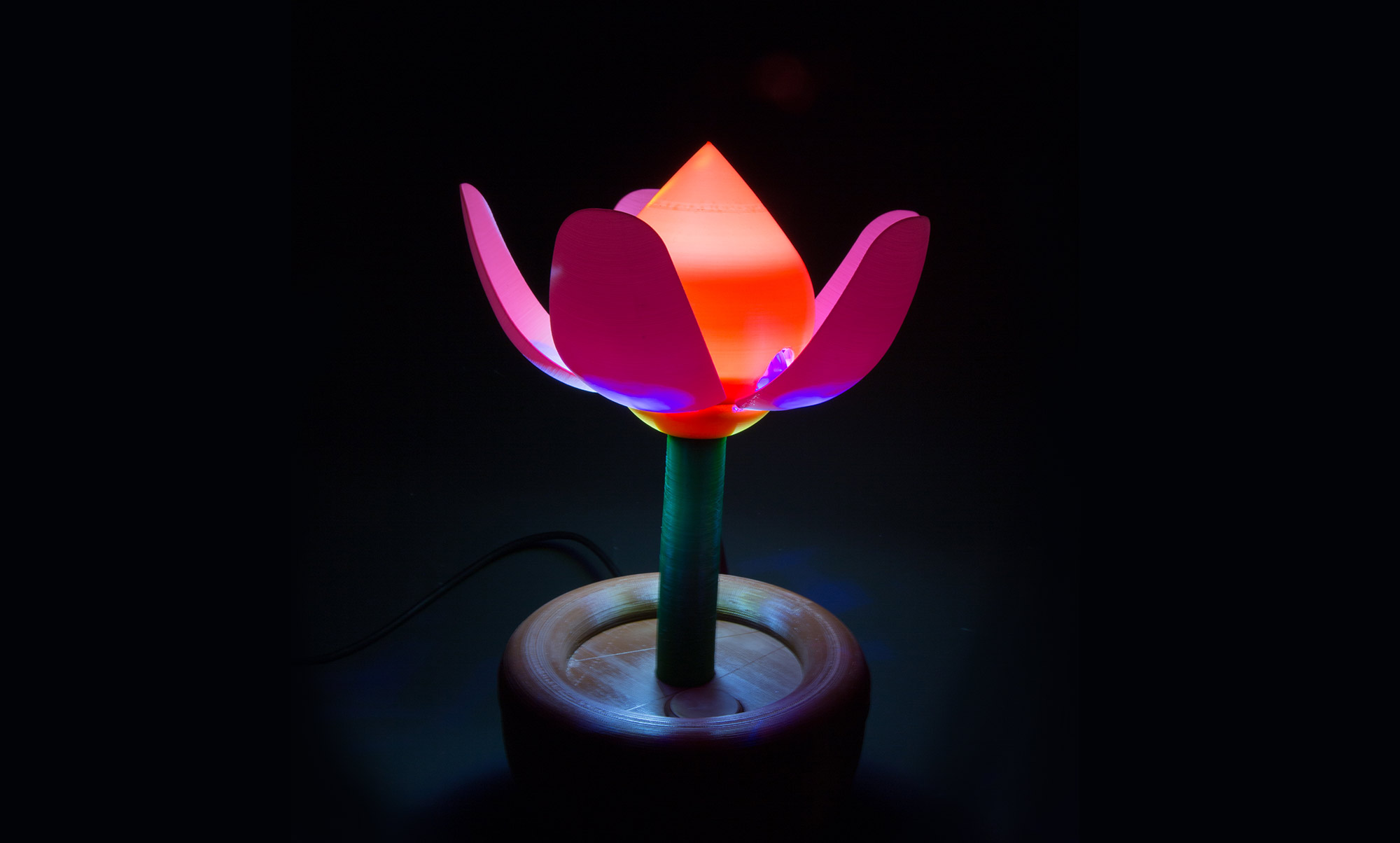
The heart of this blooming flower is a cable-actuated mechanism, which slides up and down a shaft in the center of the bloom, pulling and pushing linkages that lever the petals in and out. Full-color illumination is provided by two NeoPixel LED rings mounted back to back.

Inventive Illumination

Since the lamp receives all of its power from the 5V USB input to the Arduino, it can be powered by an old cellphone charger. In use the lamp is designed to be as accessible as possible, with a simple press of the button turning it on or off and a twist of the knob to change the color.

There is endless room for customization too, making it a great test bed for learning a bit of coding. Perhaps you’d like the lamp to turn off by itself after 30 minutes, or the colors to slowly change. Or maybe you want to add a Wi-Fi module and scrape weather pages for sunset times, turning the lamp on as the sun goes down.

Project Steps

Printing the Parts

Get the STL files (Figures 1-5) and 3D print them (Figure A). Although almost any material should work, PETG is the most suitable due to is flexibility and strong interlayer adhesion, both of which contribute to thin features (like the petals), which can take some abuse.

Figure 1
Figure A. Photo by Luke Artzt

There are a handful of things to keep in mind when printing:

MATERIAL

Although almost any material should work, PETG is the most suitable due to its flexibility and strong interlayer adhesion, both of which contribute to thin features (like the petals), which can take some abuse.

NOZZLE

I designed this for a 0.4mm nozzle; thin elements like the petals are multiples of 0.4mm thick, meaning that they print as solid pieces (0.8mm in the case of the petals and diffuser bulb)

Photo by Jason Suter

SUPPORT

Very little support material is required, and none is needed on outer visible surfaces. The overhangs on the petals and diffusor have been designed to be less than 45°, making them easy to print.

Try to avoid getting any support structures inside the various 3mm holes (for example, the slots that the petal’s pivots lie in) since it is not necessary and requires cleaning out afterward

ARRANGEMENT

Some of the parts can be printed together, such as the mechanical linkages, but I chose to print each petal and the diffuser ball as individual pieces. This is slow going, but it helps maintain perfect surfaces, especially avoiding the nasty stringing that PETG is prone to.

FOUNDATION

The majority of the parts don’t need any brim or raft, but I found it necessary on the “axis” part, since it has such a small footprint.

LEAD IN

You may want to adjust the lead in (the start point of each loop, called different things in different slicers), or you may end up with a visible line up the middle of each petal, where every loop begins and ends.

Mechanical Assembly

The mechanism and electronics all attach to the top of the pot, allowing easy access to all components until the system is complete, at which point the bottom of the pot can be installed. You can find an assembly video of the first iteration on the project page online.

Note: It’s imperative that all pivoting parts can move with as little resistance as possible. If necessary, use a 3.5mm drill bit to clear and enlarge the holes.

Test-Fit the Petals

Ensure that the petals turn smoothly on the 3mm pins (Figure B) — clean out the holes if necessary. If you can’t find smooth 3mm rod, then 15mm–22mm lengths of threaded rod or screws cut with a hacksaw will work just as well. Remove the petals.

Figure B. Photo by Luke Artzt

Insert the M3 Nuts

Place an M3 nut into each of the five hex-shaped recesses in the “receptacle lower” part (Figure C). If they’re too tight due to printer tolerances, carefully pressing them into place with a hot soldering iron works very well.

Figure C. Photo by Luke Artzt

Affix the Petals and Stem

Hang the petals into the “receptacle lower” part by the 3mm×15mm pins. Place the “receptacle upper” part over the pins. Fasten the five M3×6mm screws through both parts into the M3 nuts, locking the pins in place (Figure D). Ensure that the petals still move without resistance, then attach the “stem” to the receptacle with the five M3×8mm countersunk screws (Figure E).

Add the Linkage Assembly

Attach the long side of the five L-shaped “linkage” parts to the “linkage star” with M3×10mm screws (Figure F). The linkages should pivot freely on the screws, which are tapped directly into the linkage star.

Figure F. Photo by Luke Artzt

Screw the five linkages into the petals with M3×10mm screws, once again checking that the linkages can pivot freely on the screws (Figure G). Make sure that the hole for the cable in the linkage star and in the stem line up.

Figure G. Photo by Luke Artzt

Attach Stem to Pot

Affix the “stem” to the “pot upper” (top of the flowerpot) with five M3×10mm screws (Figure H). Insert the “axis” part through the linkage star and into the receptacle, but do not yet glue in place.

Figure H. Photo by Luke Artzt

Add Cable and Test Mechanism

Thread the stainless steel cable through the linkage star and the axis, and down the stem. Use a drop of super glue to lock the cable into the star (Figure I). Leave extra cable at the bottom of the pot (Figure J), but trim the top of the cable.


It’s important to confirm that the linkage moves smoothly and without resistance by gently pushing and pulling the cable at the bottom of the stem (depending how loose it fits, you may need to hold the axis, shown in Figure K, in place with your finger).

Figure K. Photo by Luke Artzt

Attach the Axis

Remove the axis, place it through the lower NeoPixel ring, and reinsert it, using a drop of super glue to hold it in place in the receptacle. Note that the lower NeoPixel ring must be installed first (facedown), since it will not fit over the top of the axis.

Electronics Assembly

This project uses an Arduino Nano, but it would be easily adaptable to almost any microcontroller, especially one that’s compatible with Adafruit’s Arduino libraries. To program your Nano, find the Arduino IDE.

The wiring (Figure L) is simple. Three separate subsystems — servo, LED rings, and rotary switch — each communicate with the Arduino and can be tested individually.

Figure L. Image created by Fritzing

Install the Libraries

Use the Arduino Library Manager to install:

» Adafruit NeoPixel library

» TiCoServo libraries

Attach the Microcontroller

The Arduino Nano is simply zip tied or double-sided taped to the “electronics bracket.” Its orientation is determined by whether you prefer to use the board “pins up” and intend to use jumpers (Figure M) or “pins down” and intend to solder directly to the PCB. It is easier to see the markings on the board in “pins down” orientation.

Figure M. Photo by Luke Artzt

Install the Rotary Encoder

Use the supplied nut to attach the rotary encoder to the “electronics bracket” (Figure N).

Figure N. Photo by Luke Artzt

Attach the Bracket

Affix the bracket containing the encoder and microcontroller to the flowerpot top with 4 countersunk M3×8mm screws (Figure O).

Figure O. Photo by Luke Artzt

Affix the Servo

Attach the pushrod connector to the servo horn and place the horn on the servo — but don’t screw it down yet. Use strong double-sided tape to attach the servo to the “pot upper” such that the pushrod connector lines up with the cable hole in the stem. The servo horn can be screwed on after the servo’s range of motion has been tested in the next two steps.

Wire the Servo

Since the Adafruit NeoPixel libraries conflict with the standard Arduino servo libraries, it is imperative that a hardware PWM-capable pin is used for the servo so that the “TiCoServo” library can be used. Connections are:

» 5V on Arduino to 5V on servo

» GND on Arduino to GND on servo

» D10 on Arduino to Signal on servo

Test Range of Motion

Use the sketch servoLimitTest to determine the servo positions that correspond to open and closed. First center the servo without attaching the servo horn, to prevent damaging it by mistake. Instructions on using the sketch are contained in the sketch itself as well.

» Make sure that the servoPin variable refers to the pin to which your servo is connected

» Upload the sketch to the Nano, then open the Arduino serial monitor, and

» enter the characters q or e to test the servo’s outer limits

» enter w to move to the mid point

» enter o or p to step in either direction (up to the limit)

» The servo’s current position is reported in the serial monitor, so you can determine what limits you would like to use in your final code.

Wire the NeoPixel Rings

The NeoPixels are actually strands of individually addressable WS2218 RGB LEDs, which means they can be chained by connecting the Data Out (DO) of one ring to the Data In (DI) of the next. Thread three strands of wire through the stem (Figure P) and connect them as follows:

» 5V from Arduino to Vin on both rings

» GND from Arduino to GND on both rings

» D4 on Arduino to Data In (DI) on first ring

» Data Out (DO) on first ring to DI on second ring

Figure P. Photo by Luke Artzt

Test the LEDs

It is wise to test each element of the system as you go along. Use Adafruit’s example sketch strandtest to confirm that your LED rings are working (Figure Q). Make sure to set the pin number in the sketch correctly (D4 in this case). Now you can mount both rings to the axis using bits of double-sided tape.

Figure Q. Photo by Jason Suter

Wire the Rotary Encoder

Since rotary encoders can have different pinouts, you’ll need to read the datasheet or markings on yours to determine which pins are which. The code uses hardware interrupts to handle the encoder’s movement, so it is important to use pins on the Arduino that support hardware interrupts:

» D2 from Arduino to pin A on encoder

» D3 from Arduino to pin B on encoder

» GND from Arduino to GND on encoder

» D7 on Arduino to SW on encoder

» GND from Arduino to GND on encoder switch

Once the encoder is wired up (Figure R) you can test it using the final FlowerLamp sketch, making sure that the pins are allocated as you chose them. Watch the Arduino’s serial monitor to see that turning the encoder and pressing the switch cause output messages.

Figure R. Photo by Luke Artzt

Attach the Base and Bulb

Once it’s all working, attach the “pot lower” with 10mm screws and snap the “base lid” in place. Finally, snap the clips on the diffuser “ball” to the receptacle to hold it in place (Figure S).