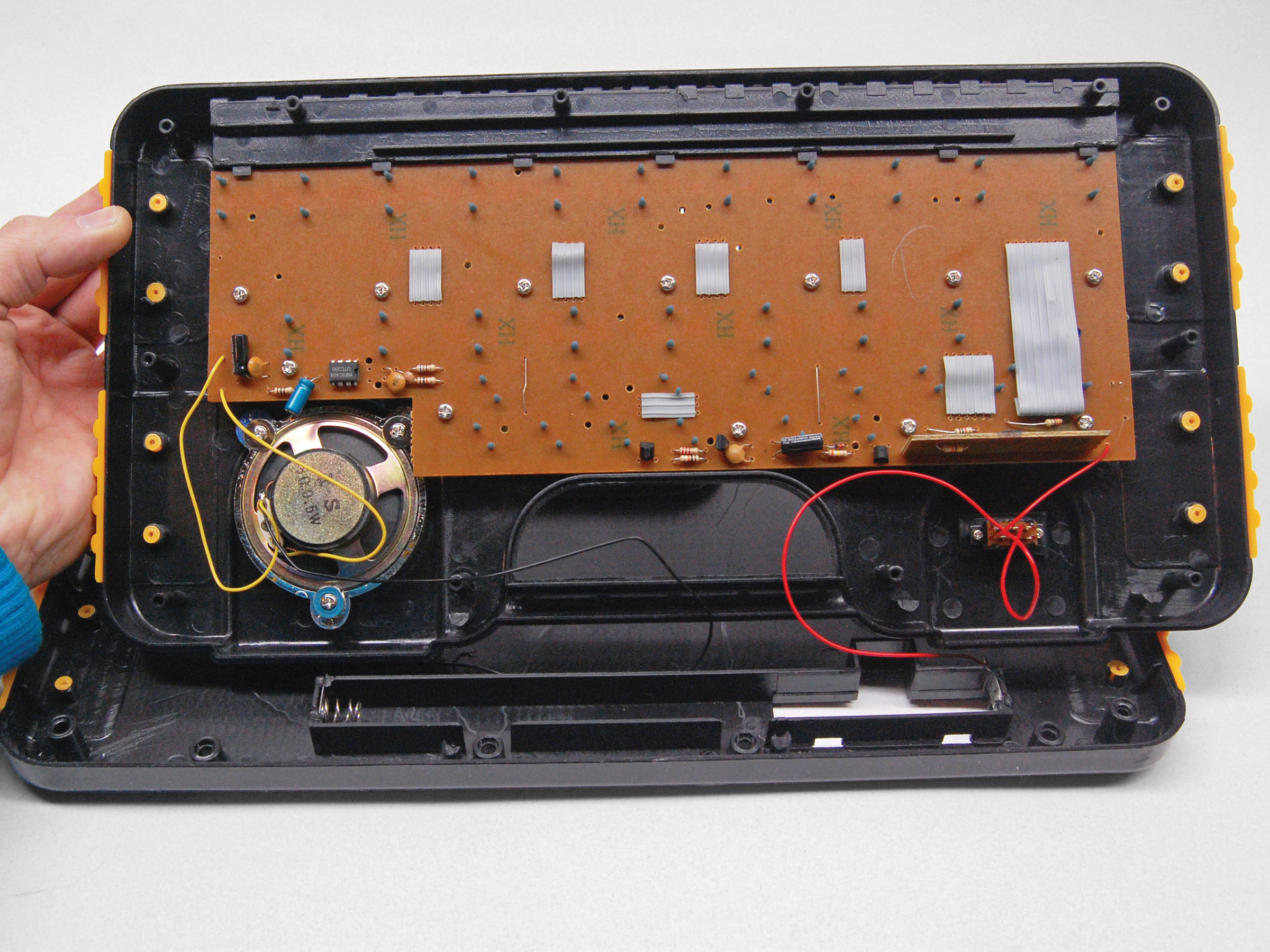
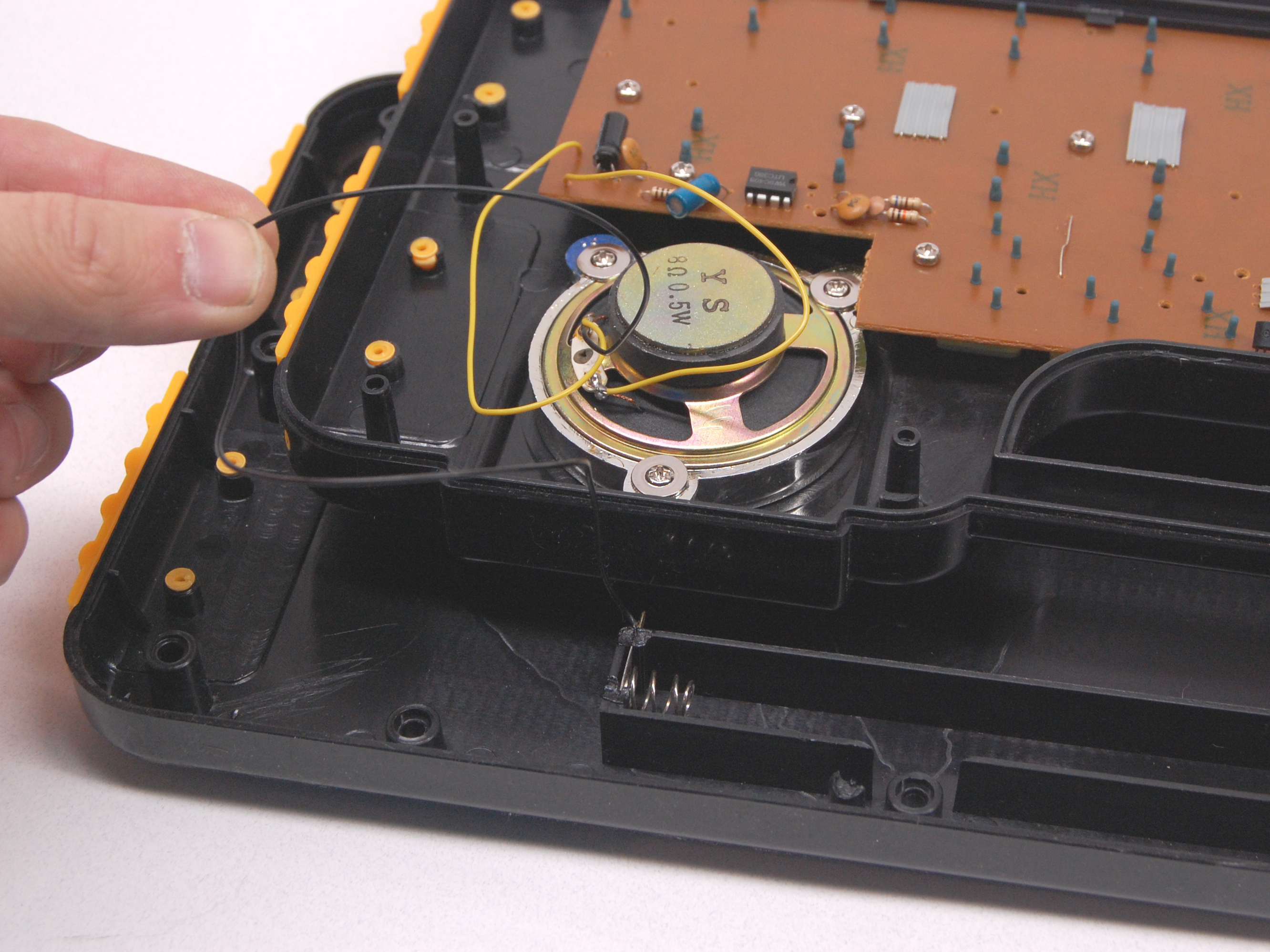
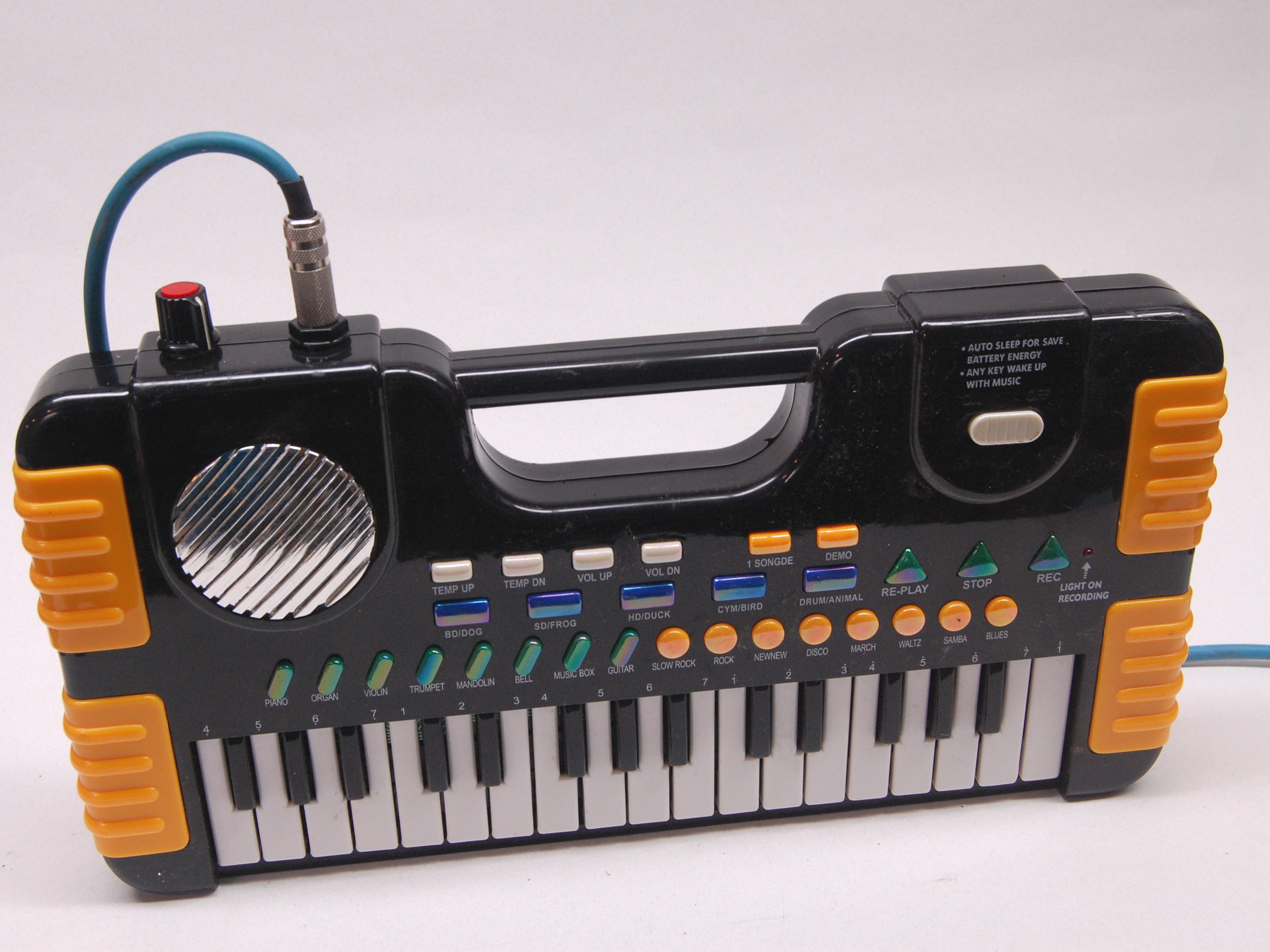
Many cheap, fun sonic and musical toys have built-in speakers and no output jack. This limits their volume, unless you constantly hold them up to a microphone. Here’s how to mod these devices so you can plug them in, adjust their volume, and rock out.

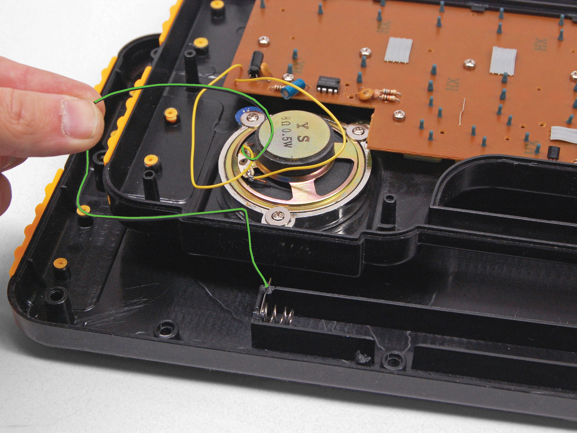
The simplest way to install an output jack is to remove the speaker and solder the jack in its place. But every time I do this I regret it, because then the toy no longer works by itself. Inevitably, there will be a time you want to play and there’s no amp around.

You can also leave the speaker connected in parallel with a regular audio jack, but then the speaker might act like a microphone and trigger feedback and unwanted noise when you’re plugged in.

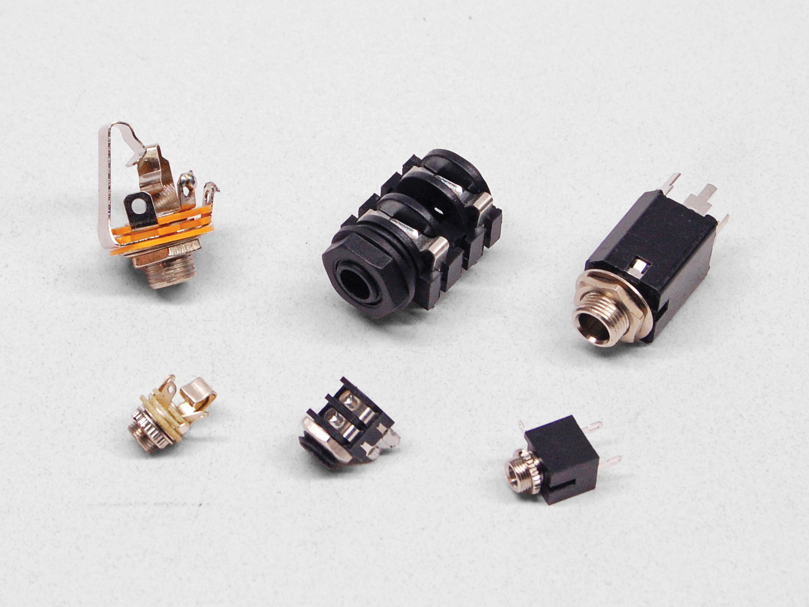
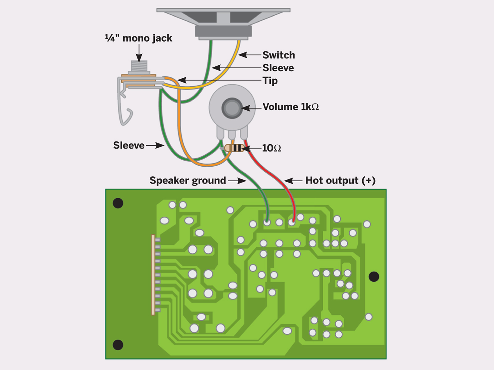
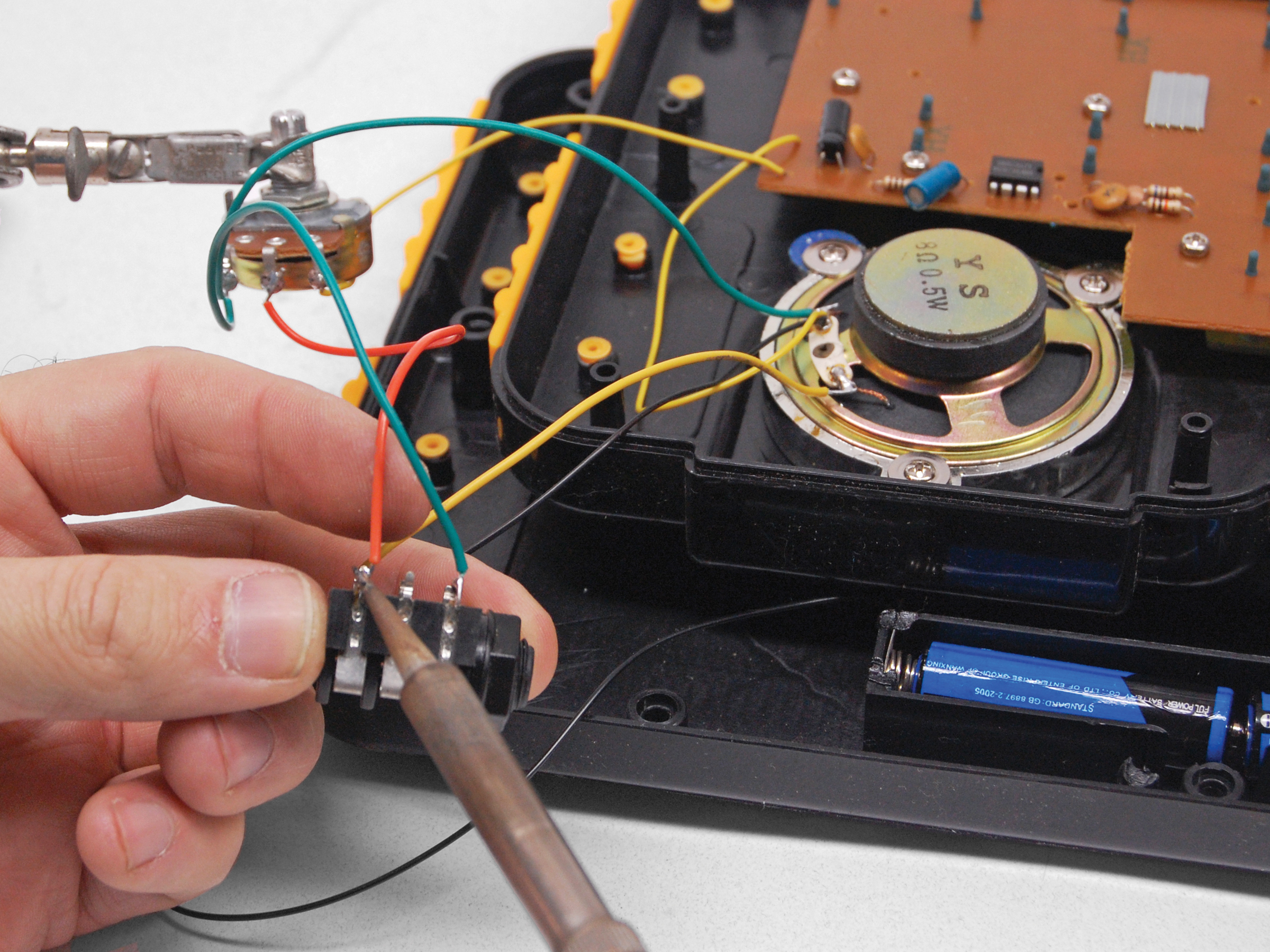
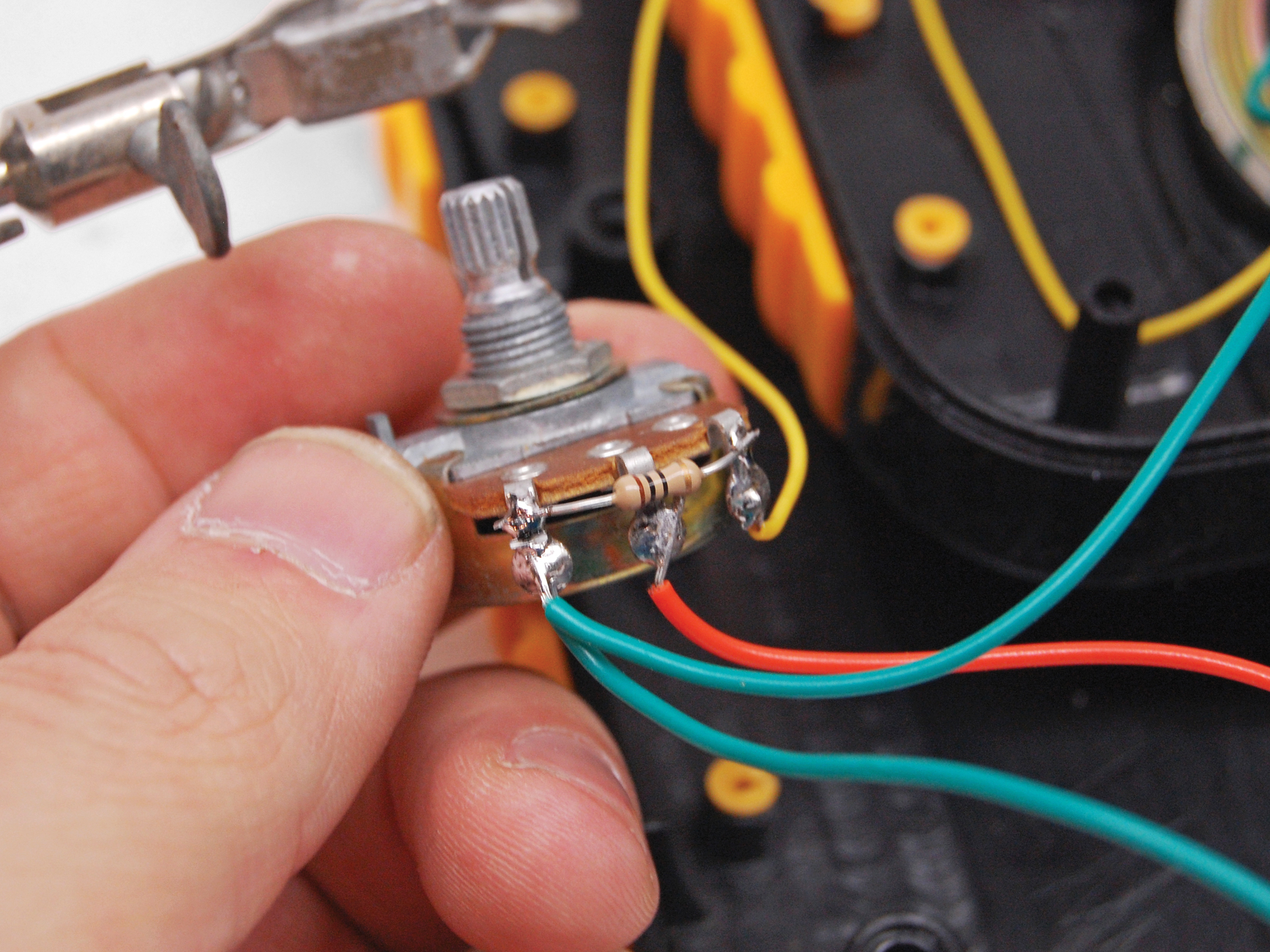
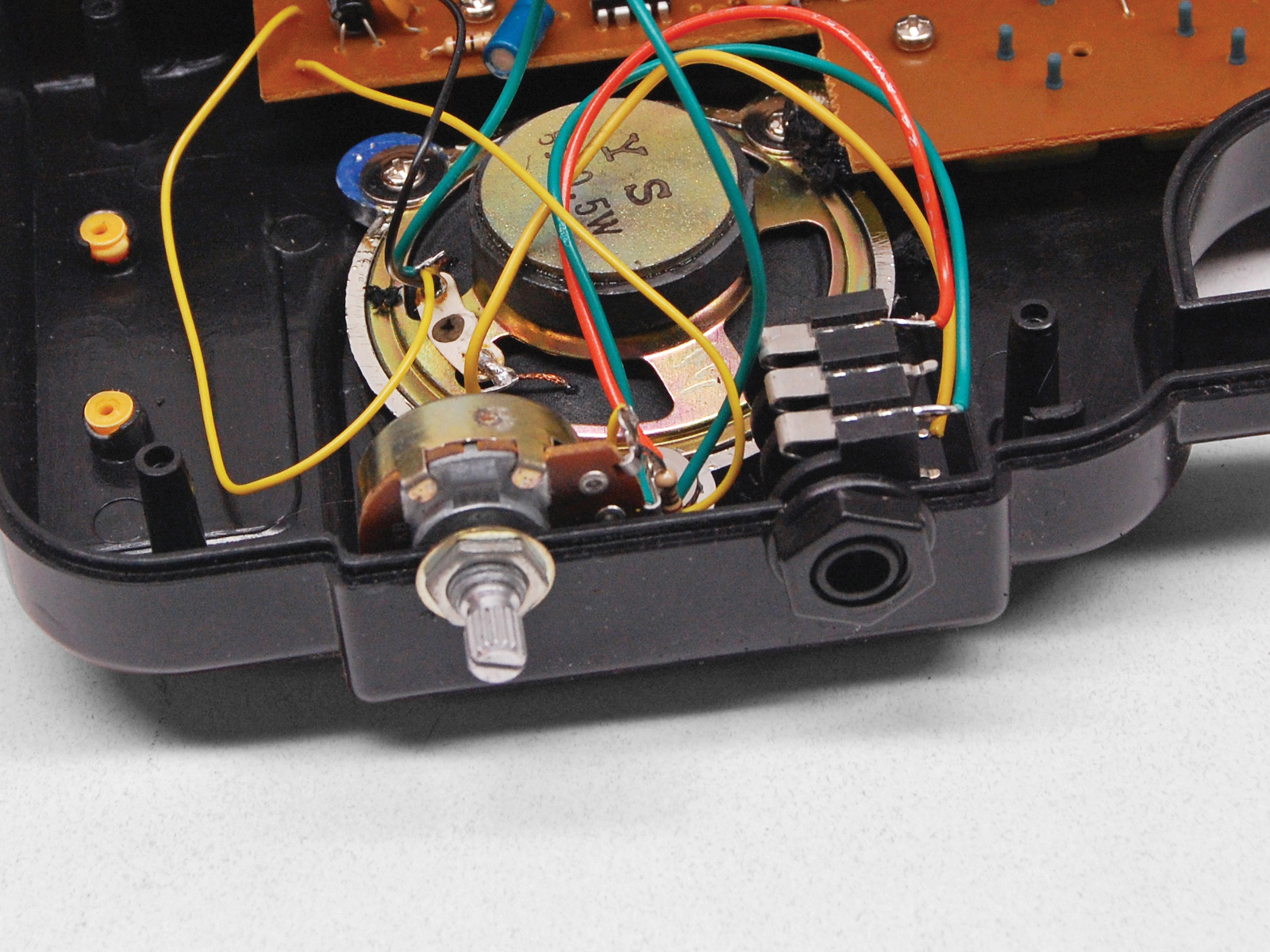
My favorite solution is to use a switching jack, which automatically disconnects the speaker when you plug in a cord. You can also use a non-switching jack and an on/off toggle that switches the speaker between standalone and plugged-in modes. But switching jacks are only slightly more expensive than non-switching jacks. Why use two pieces of hardware when one achieves the same effect?

Check out more Weekend Projects.

Project Steps

Identify your jack’s contacts.

First you need to identify three lugs of the jack: tip, sleeve, and switch. There are many different styles of jack available, so it’s hard to offer general rules for identifying these.

The second image here shows a schematic for this project with one common audio jack lug configuration. If your jack varies from this one, look for a spec sheet online.

Expose the circuit.

Open the device and find its speaker.

To keep screws in a safe place, you can usually stick them to the speaker magnet.

Unless you’re experienced with electronics, you should only work on circuits that are battery-powered or use a very low-amperage power supply (50mA or so). Poking around inside high-voltage and/or high-current circuits can be fatal.

Identify the speaker ground and hot signal lines.

Two wires connect the speaker to the circuit board: the hot signal that creates the fluctuating sound wave and the stable speaker ground that establishes the signal amplitude.

The ground attaches to the power supply (the negative contact in most pro audio gear, but toys can run either way). Once you’ve identified one wire, you know what the other one is, and you can use some tape to mark them both on your board. Here are three methods for finding the ground wire:

Follow the leads to the power supply. Follow both speaker leads out to see where they connect, continuing along traces on the board if needed. Whichever wire runs to the power supply is your speaker ground (black ground wire is highlighted green in second photo).

Use a continuity tester. Most multimeters have a continuity setting marked with an image of a speaker or sound waves. Disconnect the speaker, touch one meter probe to the positive or negative power supply, and then touch the other probe consecutively to the speaker’s contact points on the board. The speaker contact with zero resistance to either power contact is ground.

Look for a transistor or audio amplifier IC. On the board, one of the speaker wires probably connects directly to the output of a transistor or an amp IC such as the LM386. This is your hot signal.

Wire up the pot and jack.

On your potentiometer, decide which leg will be the ground and which will be hot (the middle leg is always the sweep).

Solder wire connections as follows: jack tip to pot sweep; jack switch to one side of the speaker; jack sleeve to the other side of the speaker and to pot ground; pot ground to speaker ground on the board; pot hot to hot output on the board.

Make the wires long enough to give wiggle room for mounting the controls.

Test it!

Plug the device into an amplifier and play it.

If it sounds distorted, solder a 10Ω resistor between the hot and ground legs of the potentiometer, as shown here.

If the signal is too loud for your liking, you can also add a 1Ω–10Ω resistor between the potentiometer and the output jack.

Mount the pot and jack.

Choose and mark locations where the volume and output jack can fit on the toy’s casing, then use a drill or Dremel tool to create the appropriate-sized holes.

If you place your holes along a seam, use a high-speed Dremel to remove the plastic with a cutting/routing bit. An ordinary drill would simply push the halves apart or split the plastic.

Mount the hardware and put the knob on the pot. Once that’s done, carefully close up the housing, but don’t screw it back together yet.

Retest and assemble.

In the process of closing the housing, it’s likely that you moved around and possibly severed some of your wiring.

Test the device again, both plugged-in and unplugged, to make sure it still works.

If so, screw the housing back together, and you’re ready to rock.

Conclusion

Adapted from an article by Peter Edwards in MAKE Volume 24.