




Featured image by NASA. All other images by Forrest M. Mims III.


Cover of Make Volume 98. Headline is "Action: Projects that go Zoom! Bang! Woosh!". A small, ultralight drone that weighs less than 3 nickels is featured on the cover above a banana for scale.
This article appeared in Make: Vol. 98. Subscribe to Make: for the latest articles.

The ozone layer envelops the entire Earth and protects us all — animals and plants — from most of the sun’s dangerous ultraviolet rays. While there is some ozone at the surface, the main ozone layer begins at the bottom of the stratosphere, just above the troposphere where we live and where weather occurs. This boundary is called the tropopause

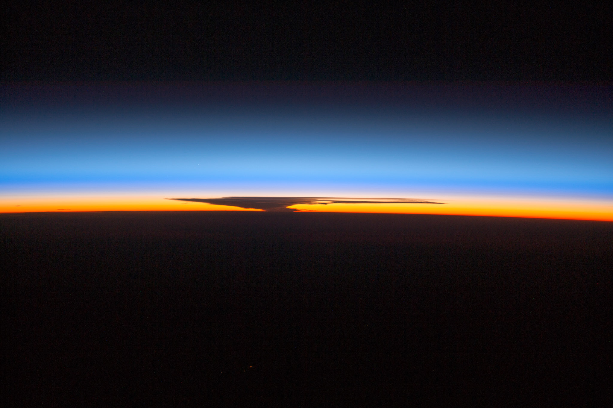
You can see where the tropopause merges into the stratosphere when a major thunderstorm is nearby. The anvil-shaped top of these storms flattens out at the tropopause.

Astronauts can see the ozone layer when the sun is just below the horizon. The featured image above is a 2014 photograph made by astronauts aboard the International Space Station (ISS) at sunset over Papua, New Guinea, that shows a very large thunderhead over Australia 1,500km (900 miles) away. The orange layer is the upper troposphere. The stratosphere begins at the tropopause just above the thunderhead, and the thick blue layer is the main section of the ozone layer. (For more details, search online for “ISS041-E-105277".) The lighter blue is the mesosphere.

The ISS photo suggests that ozone forms a thick, protective layer. But if all the ozone over your head were brought down to sea level, atmospheric pressure would compress it to a layer only 2.5 to 3.5 millimeters thick (0.1 to 0.14 inch). That’s around the thickness of a stack of two pennies!

In the central United States, the peak thickness of the ozone layer occurs at an altitude of around 25km (15.5 miles), and it thins out at around 40km (24.85 miles). Because of aerosol interference, a twilight photometer can measure the height of the ozone layer much more accurately than the full profile.

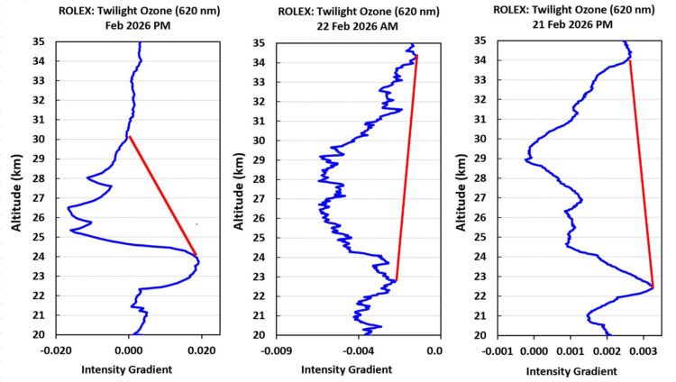
Morning and evening ozone height change during a single day.

This shows how the peak altitude of the ozone layer can change significantly during a single day when stratospheric disturbances occur. At least that’s what Grok suggested when I reported this unusual pair of plots, which were made from my field in Texas the morning and evening of the same day.

You can see various ozone profiles measured by satellites by searching online or using Grok, ChatGPT, and other AI resources.

NOTE: Most ozone layer plots show the peak ozone on the right side of the chart. This is reversed when plotting twilight photometer data, which indicate a decline in the twilight signal when ozone
is present.

Atmospheric scientists track the ozone layer’s altitude because of its role in atmospheric circulation, rainfall, and studies of ozone’s recovery from losses caused by CFCs. I track its altitude for the same reasons, and to look for unexpected changes caused by unknown reasons.

Measuring the peak height of the ozone layer is the objective of this article. We will follow the footsteps of ozone pioneer F.W.P. Götz, who in 1930 made the first measurements of the height of the ozone layer over Arosa, Switzerland, with a bulky Dobson spectrophotometer pointed at the sun. I am very familiar with this instrument, for in 2016 I calibrated the world standard Dobson for NOAA during two months at Hawaii’s Mauna Loa Observatory.

Extracting the height of the ozone layer from Dobson measurements is not simple, so there is now much more interest in satellite ozone data. I have long wanted to develop a much simpler ground-based method based on twilight photometry.

While the strongest absorption of ozone occurs in the ultraviolet (UV) wavelengths, the French chemist and physicist James Chappuis discovered in 1880 that a broad band of visible light peaking at 575nm (yellow) and 603nm (orange) is also absorbed by ozone. In 1954, O.R. Wulf of the Smithsonian Astrophysical Observatory found variations in the ozone column during twilight caused by this Chappuis absorption.

I finally succeeded in measuring the height of the ozone layer with a twilight photometer on July 20, 2016, at the Mauna Loa Observatory using a 620nm LED for a detector (detection peak around 600nm) and an op-amp with a huge feedback resistor of 20 gigohms (GΩ). The peak ozone layer height from the photometer was 25.3km (15.7 miles) while a balloon-launched ozonometer launched from Hilo measured the peak height at 25.9km (16.1 miles), a difference of only 0.6km (0.4 mile) or about 2.5%.

Twilight Photometry

It is rather astonishing that a handheld instrument can accurately measure the height of the tropopause (10–15km or 6.2–9.3 miles), aerosol layers (5–25km or 3.1–15.5 miles), the ozone layer (25–35km or 15.5–21.8 miles), and even meteor smoke in the thermosphere (80–110km or 49.7–68.4 miles).

You can acquire these results during twilight by pointing straight up at the sky a filtered photodiode or LED connected to a very high-gain amplifier. This instrument is a twilight photometer, and construction details for one of my earliest were published in Make: Volume 44 (makezine.com/projects/twilight-photometer) and also in my book Make: Forrest Mims’ Science Experiments.

Here we will cover how twilight photometry can be achieved with a suitable LED mounted at the focus of a small telescope. The telescope is pointed straight up for an hour or more before sunrise, or after sunset. The LED will observe the light from the edge of Earth’s shadow as it rises or falls in altitude during twilight. The LED’s signal is amplified, stored in a data logger, and later processed in a spreadsheet program such as Excel.

My twilight photometry research described in Make: led to an assignment from NASA’s Dr. Dong Wu to develop twilight photometers to measure the altitude of aerosols from the historic eruption of the Hunga Tonga undersea volcano in 2022. For that project, I retained Hagerup Technical Services to construct five twilight photometers using LEDs as photodiodes.

While conducting Hunga Tonga aerosol measurements, I noticed that the NASA photometers found the altitude of the tropopause by detecting a subtle change in aerosols that occurs there. Earlier researchers mentioned this possibility, but never pursued it. Our many twilight measurements were within a few percent of the tropopause measured by weather balloons launched by the National Weather Service. This finding was so significant that Dong and I wrote a formal paper in 2024, “Tropopause Height Inferred from Twilight Photometry” in Bulletin of the American Meteorological Society (doi.org/10.1175/BAMS-D-24-0054.1).

The tropopause is the boundary between the troposphere, where weather occurs, and the very stable stratosphere, where the ozone layer occurs. It is typically 9–12km (5.6–7.5 miles) high over the U.S. When possible, aircraft pilots prefer to fly above the tropopause where the air is much more stable.

Ultra-Sensitive Ozone Layer Twilight Photometer

My first twilight photometers used conventional, low-noise op-amps with ultra-high-resistance feedback resistors.

The NASA-inspired photometers used a 1" telescope and an Analog Devices ADA4530, a relatively expensive surface-mount (SMD) op-amp that can amplify the photocurrent from an LED a trillion times. This ultra-high amplification provides less noise than my previous photometers.

The NASA twilight project led to a grant from Rolex to develop a much simpler photometer with even less noise than the NASA-sponsored units. While the NASA instruments worked well, I designed a much simpler circuit that used only an ADA4530, a 5GΩ or 10GΩ feedback resistor, and a small feedback capacitor (~10pF–20pF).

For the first time since I began twilight research in 2013, the new ultra-simple design sponsored by Rolex displayed a sharp negative spike at the tropopause rather than the slight dimple displayed by the NASA photometers. This spike was caused by a sharp drop in aerosols that clearly indicates the tropopause.

Building an ADA4530 Twilight Photometer

There are various ways to assemble a twilight photometer using the ADA4530 chip. Some are much less costly than the method described here. For example, you can use a $3 Fresnel lens instead of the expensive Thorlabs telescope I used.

Either way, the ADA4530 chip ($30–$40) and an LED are installed on a tiny 7/8"-diameter printed circuit board that fits inside a telescope tube. My friend Don Wilcher designed the board and arranged for its fabrication.
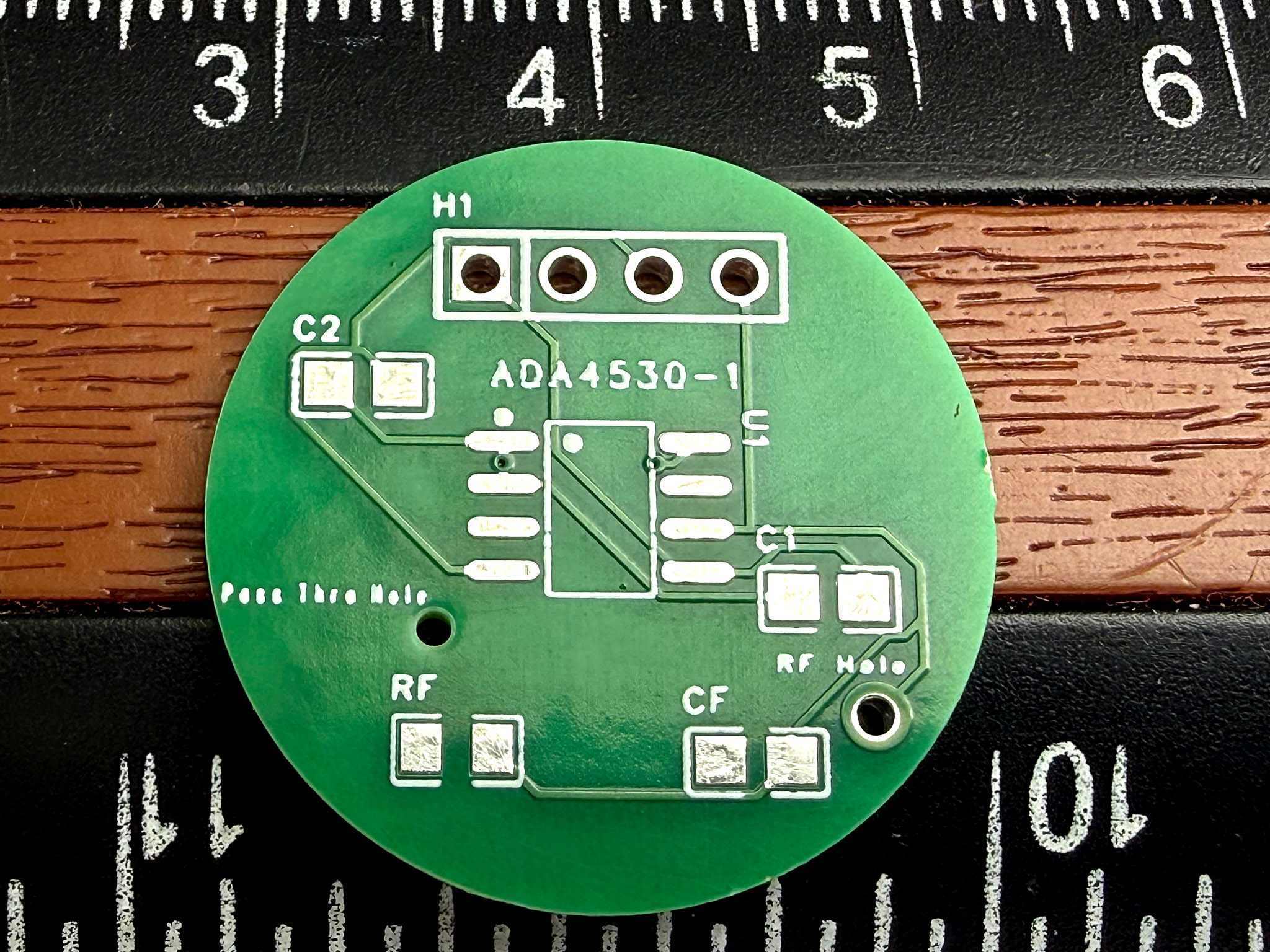
Project Steps

1. Clean

Cleanliness and a dust-free room are essential when assembling an ultra-high-gain twilight photometer. While holding the circuit board by its edges with clean hands, thoroughly wipe both sides with a clean paper towel soaked in isopropyl alcohol. Allow the alcohol to stay on the board for a few minutes. Then hold the board securely by its edges and blow away the alcohol with a blast from a canned air duster.

2. Assemble Circuit

Your best friends here are a hands-free method of holding the circuit board, along with disposable vinyl gloves and a head-mounted magnifier with an LED illuminator. Begin assembly by placing the dry board atop a clean saucer with the copper pads facing up. Keep it in place with a bit of masking tape.

2a. Capacitor

Next, solder C1 to the board. Be sure to hold the tiny capacitor with tweezers and do not touch it or the surface of the board with your bare fingers. Apply a thin layer of solder to one of the two pads for C1. Then carefully place the two ends of C1 over its two pads and secure it in place with tweezers or masking tape. Carefully touch the soldering iron to the junction of the chip and the solder-covered pad. The capacitor should remain in place. Touch a solder wire to the junction of the second pad and the circuit board. The solder should flow around this end of C1 and secure it to the board.

For more tips on surface-mount soldering, see the last step of this article.

2b. Amplifier chip

The gain of the ADA4530 is so high that the chip is extremely sensitive to anything touching pin 8, the input pin to which the signal from the LED used as a photodiode will be connected. Therefore, pin 8 must be very carefully bent, from straight down to straight away from the chip, before its remaining seven pins are soldered to the board.

Bending pin 8 requires considerable care to avoid dropping the expensive chip, which might bounce off the paper towel and disappear on the floor. My approach is to hold the ADA4530 with the narrow jaws of clean needlenose pliers and use clean SMD tweezers to carefully bend pin 8 outward so it is perpendicular to the chip. (Be sure to wipe the pliers and tweezers with isopropyl alcohol before using them.) I have used this method for a dozen or more ADA4530 SMD chips, and none were dropped. If you have any spare SMD ICs, practice this procedure before doing so with the expensive ADA4530.

Set the ADA4530 on a clean paper towel. On the circuit board, carefully place a thin layer of solder over the pads for pins 1 and 5 of the ADA4530. Remove excess solder with solder wick. While wearing disposable vinyl gloves, secure the chip to the board with a bit of masking tape across pins 3, 4, 5, and 6. Then very carefully touch your soldering iron to where pin 1 of the IC touches its solder-coated pad. If the ADA4530 is properly aligned, carefully remove the tape and solder pin 5 to the board. Complete the installation of the ADA4530 by touching the remaining pins with the iron and solder wire. Use your magnifier to be sure all seven pins are properly soldered.

2c. Mini connector

Next, insert the four pins of a 4-conductor mini connector socket into their holes on the top side of the board and then solder them in place on the back side.

2d. LED

Cut a square of vinyl tape or Velcro-style hook-and-loop tape and apply it to the back side of the board where the LED will be installed. This insulates the LED from the board. Be sure to leave the holes through the board open.

A 620nm red LED is soldered to the back side of the board. I have used both wire-lead and surface-mounted LEDs with extended, flat terminals, the latter of which I prefer. The positive pin, marked with a “+” sign, is soldered between the two center pins of the mini connector on the back side of the board.

While still wearing vinyl gloves, add solder between the two center pins of the connector. Then press the LED’s anode terminal against the two connector pins and heat with your soldering iron until the terminal is melted into the solder between them.

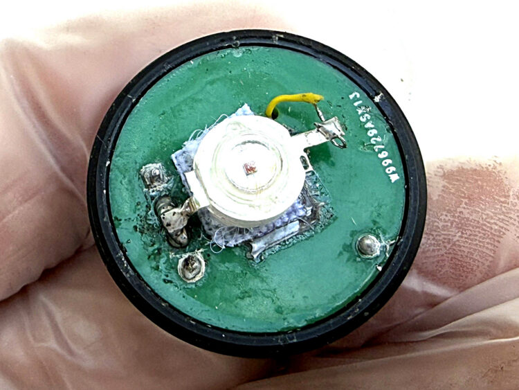
Carefully remove the insulation from both ends of a 1" length of thin hookup wire and solder one end to the LED’s cathode terminal. (Bend the terminal slightly upward if it is touching the board.) Insert the other end of the wire through the pass-through hole in the board. It will be connected later. This shows the back side of the board with the LED soldered in place.

Lower side of circuit board showing the LED. Note that the LED anode is soldered to the junction of two center tabs from the socket on the front side of the board.

2e. Feedback resistor and capacitor

It is essential to wear vinyl gloves for the next step to avoid touching RF, a 5GΩ or 10GΩ resistor, and CF with bare fingers.

First, carefully solder the leads of CF, a 10pF or 20pF capacitor, across the leads of RF. The capacitor should be just below the resistor but not touching it. Clip off CF’s excess leads.

Soak the combined RF + CF for several minutes in a clean water bottle cap filled with isopropyl alcohol to remove all impurities. Agitate RF and CF within the alcohol before removing them. Then hold RF and CF with clean tweezers and blow the alcohol away with a duster.

Very carefully insert one lead from RF through the hole between the pads for C1 and CF and solder the lead in place.

Bend the second lead from RF + CF across the board and solder it to the thin wire from the LED that you inserted from the back side. The board is completed by carefully soldering a short length of insulated wrapping wire between this junction and the unconnected pin 8 of the ADA4530.

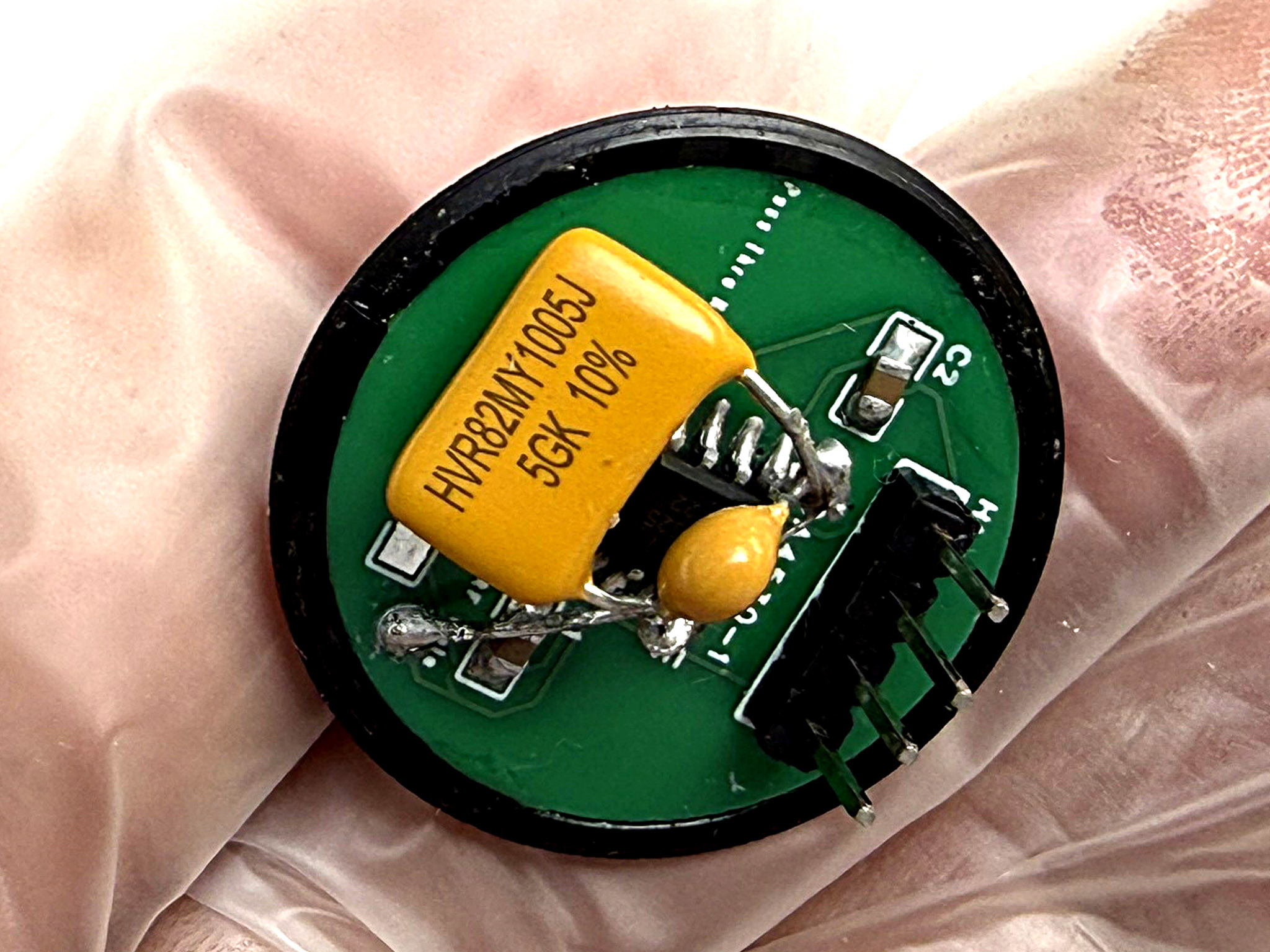
These photos show the board’s top, bare and assembled. The large orange component is RF, a 5GΩ feedback resistor (use 10GΩ for more sensitivity). The round object below it is the feedback capacitor CF soldered to the leads of RF. These components and the board itself should be touched only when you are wearing disposable vinyl gloves.

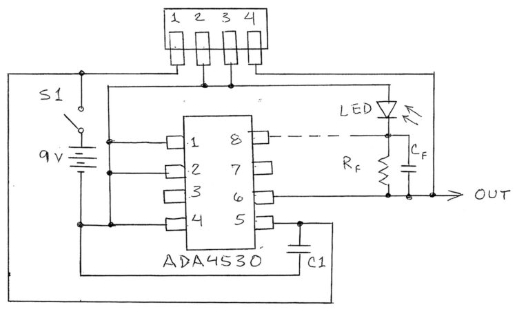
The circuit diagram shows how the various connections are made between the circuit board, 4-pin plug and socket, the power switch, the 9V battery, and the Onset 16-bit data logger. After the external connections have been made, dip the entire assembled board into a small container filled with isopropyl alcohol and gently shake the board for 30 seconds or so. This will remove dust and other contaminants that will greatly reduce the circuit’s sensitivity. Remove the board and spray away the alcohol with a burst from a duster, and install the board into the end of the lens tube.

3. Enclosure and Lens

For best results, the photometer’s LED should look at the twilight glow through a magnifying lens with a narrow field of view. While you can use an inexpensive plastic Fresnel lens, I used a high-quality glass lens and lens tubes from Thorlabs identical to those in the NASA photometers (see Materials list). These provide stability, but they can be replaced by an inexpensive Fresnel lens about the size of a credit card, cemented 1 focal length away from the LED.

Thorlabs sells a wide variety of threaded tubes for their lenses. These tubes come with internal threaded rings. The rings that came inside the tubes I ordered fit perfectly around the 7/8" circuit board designed by Don Wilcher. Inserting the assembled board into a threaded ring permits the focus to be adjusted, and also allows the circuit to be removed for troubleshooting or for changing the LED.

Select a ring that fits tightly around the circuit board. While wearing disposable vinyl gloves, carefully cement the board to the inside of the ring with a very thin line of cement. I used Gorilla Clear Grip. Make sure no cement touches the threads, for that will prevent the ringed board from being inserted into a lens tube.

I assembled my photometer inside a 2¾"×2¾"×5½" tin enclosure from Hobby Lobby. I drilled a 1" hole through the center of the enclosure’s bottom using a step drill. This is best done by inserting a 4" scrap of 3×3 lumber into the enclosure. Hold the enclosure straight up with the wood roughly centered inside and resting on a flat surface. Begin carefully drilling through the center of the enclosure’s bottom until the hole is 1" across. Wear leather gloves to avoid scratching your fingers.

After the hole is carefully smoothed, insert the threaded end of a Thorlabs lens tube into the outside of the hole and screw it into a second lens tube inside the enclosure. Then push a 4" section of hollow black plastic pipe insulating foam over the internal lens tube. This provides a firmly centered mount for the circular circuit board installed inside a threaded ring.

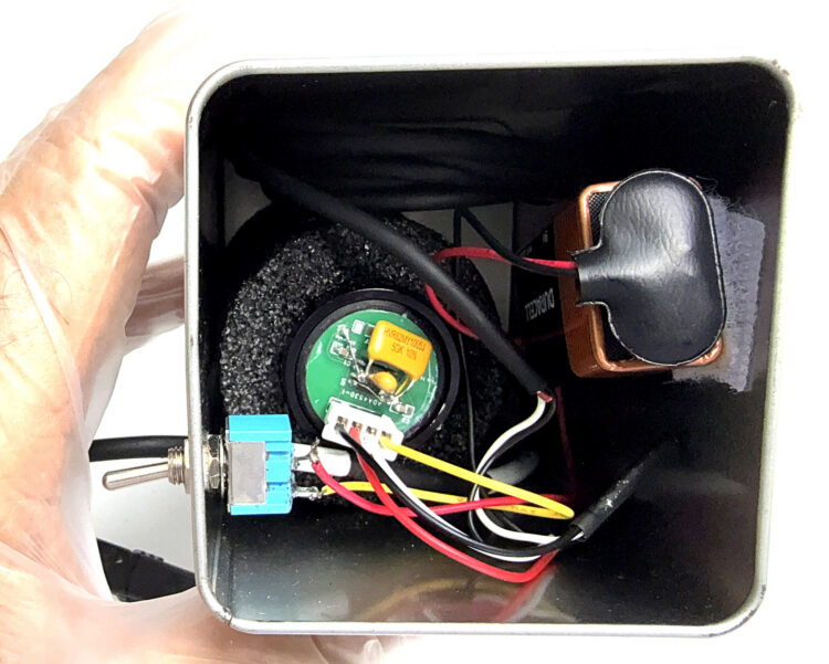
Next, drill two 1/8" holes near the base of the enclosure, one for the power switch and one for the data logger cable. The wires from the 4-conductor connector are then connected as shown. Coil the input cable for the data logger and insert it between the foam cylinder and the enclosure wall as shown . The 9V battery can be mounted to the wall with 1" squares of self-stick velcro tape.

Circuit board installed in lens tube and connected to on-off switch, 9V battery, and data logger cable.

While wearing vinyl gloves, carefully screw the assembled circuit board into the end of the 3"-long tube that mates with the end of the interior 3" tube.

It is extremely important to avoid routing any of the external wires over the circuit board. Besides contaminating the board, they might press RF and CF onto the ADA4530. Therefore, all external wires must be placed around, and never over, the exposed circuit board.

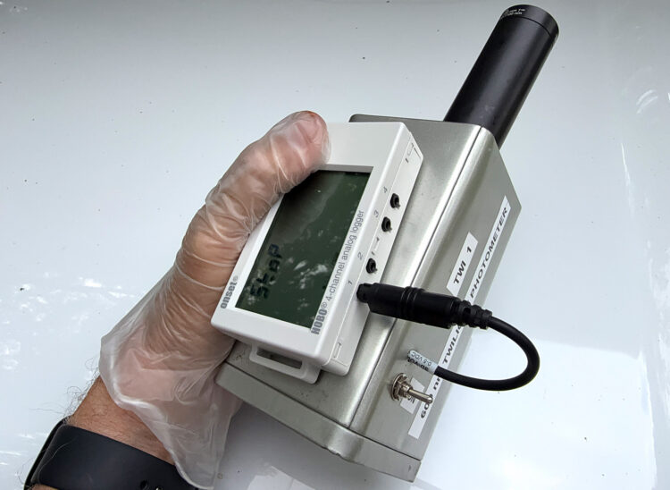
Finally, install the Thorlabs lens over the end of the external tube. First, blow away dust from both sides of the lens. Use a Thorlabs lens cap or a small plastic bag to protect the lens when the photometer is not in use. This image shows the assembled twilight photometer before an evening twilight session.

Completed twilight photometer.

Using Your Ozone Photometer

The completed photometer should be placed on a flat surface well away from artificial lights. I place a plastic level across the lenses of my photometers and use plastic furniture levels to make sure they are perfectly level before taking twilight measurements.

Various websites provide the exact time for sunset and sunrise at your location. I set up my instruments and switch them on around 10 minutes before sunset and an hour before sunrise. At my location (29.6 degrees North), an observation time of 1 hour will provide data from the ground to around 150km (93 miles). While a clear sky is ideal, data can often be collected through thin clouds.

Processing the Data

My previous twilight photometry article in Make: provides full details on how to interpret the instrument’s output during twilight. Back then my major interest was finding bulges in the data plot caused by aerosols in the upper atmosphere from African dust, forest fire smoke, and the aerosols around 20km known as the Junge layer. (For those aerosols, near-infrared LEDs work best.)

The peak height of the ozone layer varies over time. At my latitude of 29.6 degrees, the peak can range from 20–30km. Here are three typical plots during cloud-free twilights with an average peak of 27km. Fluctuations in the traces are mainly caused by aerosols, which is why I am experimenting with simultaneous measurements at 885nm, where ozone absorption is very low and aerosol effects can be problematic.

Three ozone layer peaks measured by the twilight photometer from Mims’ Texas field.

The average peak of 11 of my twilight ozone measurements made while preparing this article was 25.13km — almost equal to the NASA average over my site of 25km.

More ozone science: epa.gov/ozone-layer-protection

How to Install Surface-Mount Components

Twenty years ago, Heathkit hired me to develop a surface-mount training product complete with two manuals and parts. While some of the components I used back then are now smaller, the assembly components I used back then have not changed. They include a head-mounted magnifying lens or lenses (preferably with a built-in lamp), SMD tweezers, needlenose pliers, a sharply pointed soldering iron, and a dose of patience.

Some SMD tool suppliers include a practice board and a strip of SMD parts with their products. This allows you to practice preparing an SMD board, mounting the parts, and soldering them in place.

Begin a practice session by placing a clean sheet of textured paper towel on your work table, and tape its corners to your work surface. Place your soldering iron and tools on either side of the paper towel. Next, carefully clean both sides of the SMD circuit board while holding it by its edges between your thumb and forefinger. Do not touch the circuit side of the board after it is clean and shiny. Use a small square of masking tape to hold the board with its conductive traces facing up to the clean side of a 3×5 card placed on the paper towel.

Next, place the SMDs on the paper towel. (Don’t even think about sneezing!) SMD resistors and capacitors are easily soldered across two pads on the board. Touch the point of your iron to one of the two pads for a second or two, and then touch a thin length of solder to where the iron touches the pad. Your goal is to place a thin layer of solder on the pad. If the solder layer bulges upward, remove excessive solder from the pad with desoldering wick.

Next, place the SMD component over the two pads and hold it in place with tweezers or a piece of masking tape. Then touch the point of your soldering iron to where the component rests on the second pad and melt a bit of solder between the unsoldered pad and the SMD part.

Soldering SMD ICs is a bit trickier but can be achieved with practice. My approach is to apply a thin layer of solder to the pads for two opposite corners of the IC. I then hold the chip in place with a bit of masking tape and solder those two pins. When the pins are soldered exactly in place, I then very carefully solder the remaining terminals. Avoid excess solder. If you accidentally bridge two adjacent contacts and pads with solder, remove the bridge with desoldering wick.


This article appeared in Make: Volume 98.