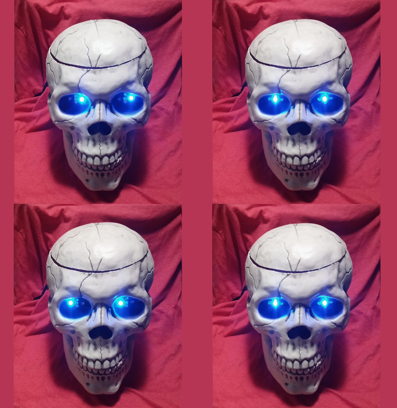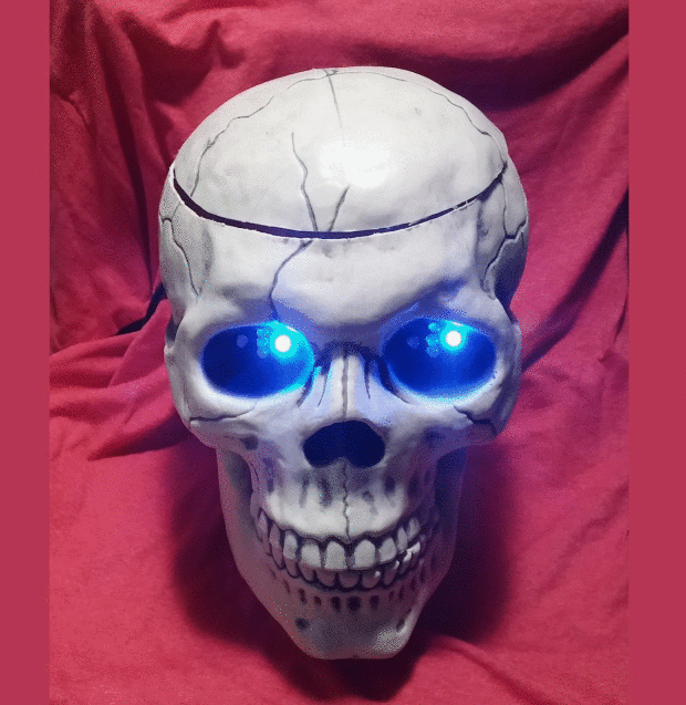
Image: Andrew Terranova
Scully, a fellow of infinite jest. Photo: Andrew Terranova

Halloween is fast approaching, so it’s time to break out the animatronics! I hunted around and found a great plastic skull to work with. It’s extra large and hollow… perfect for my idea: an animatronic skull candy jar to give those trick-or-treaters a bit of a spooky thrill.

As a visitor approaches the skull, they will see its cool blue eyes regarding them. The eyes move up, down, left, right, and all around, and blink randomly as well.

As our brave trick-or-treater comes closer, the skull’s Passive InfraRed (PIR) sensor will detect their movement. The eyes will suddenly turn red, and a creepy voice will laugh and say, “Take one,” offering a piece of candy from the skull’s now open lid. Finally, with a jaunty “Happy Halloween” the skull’s eyes will flash purple in warning, and the lid will slowly close.

This is a fun build that will require some use of a rotary cutting tool, hot glue gun, drilling, and soldering. Not scared away yet? Good, give it a try!

You can record your own sound effects and customize the eyes, jaw, and lid movements. If you build this project, please post links to pictures and videos. I’d love to see your take on it. Below is a video of the skull (I think I’ll call him Scully) being tested.

YouTube player

Project Steps

Mark the skull for cutting

Select a hollow plastic skull large enough to fit a candy bowl and electronics inside. The jaw should be moveable.

Take the skull and mark a line around the top where you will cut out the lid.

Cut the skull

NOTE: In this step DO NOT cut all the way around. Leave about 1 inch un-cut in the back to act as a hinge. I scored the plastic a bit to make it easier to bend, but was careful not to cut all the way through.

Use your rotary tool to cut along the marked line, leaving 1 inch in the back as a hinge.

Attach the lid servo

Take one of the servos and attach it with hot glue to the inside of the skull at the back. The servo horn should be aligned with the center of the skull.
Attach a long servo horn, making sure that the horn will not hit the back of the skull when at maximum rotation towards the top.

Cut a piece of the brass rod about 4 inches long. Make a 90° bend on one end, and a squared-off hook on the other. Loop the hook through the hole in the servo horn furthest away from the servo.

Use hot glue to form a pivot point around the 90° bend in the brass rod and attach to the lid of the skull. The skull I bought had a small hole at the top, which is where I attached the hot glue pivot.

Position the jaw servo

Cut a piece of the brass rod about 4 inches long. Make a squared-off hook on one end, and loop the hook through the hole in the servo horn furthest away from the servo.

Take the second servo and position it inside the skull at the bottom. Attach the servo so the horn will face the front of the skull.

Attach the servo horn, making sure that when at maximum rotation towards the front of the skull, the horn does not hit the bottom of the skull.

Cut a slot in the bottom of the skull for the brass control rod, which will connect to the inside of the skull’s jaw. The slot should be centered where the servo horn will be, and positioned so that when the servo moves the control rod can move freely. This may take some trial and error.

Attach the jaw control rod and secure the servo

Check where the brass control rod from the jaw servo will be positioned when it is inserted through the slot cut in the last step. Drill a 7/64 inch hole in the jaw as shown, for the rod to hook onto.

Make U-bend in the end of the brass control rod as shown. Insert it into the hole you drilled in the jaw and hot glue it in place.

Get everything aligned so that the jaw servo can fully open and close the jaw when the servo moves. This will take some trial and error.

Once you have everything lined up the way you want it, attach the jaw servo inside the skull at the bottom with a lot of hot glue. Reinforce it with more hot glue, to prevent the servo from popping loose under load.

Cut the circuit boards for the eyes

Snap the Radio Shack Dual Mini Board in half along the center perforation. Oddly enough, one half of the mini board has 213 holes, and the other has 228. Take the side with 228 holes, and set the other half aside.

CAUTION: You should wear a protective respirator mask to avoid breathing in particulates when you cut the board in this step.

Use a rotary cutting tool to cut the circuit board in half again. If you can, leave a column of eight contact holes on each side of the cut.

Note that I accidentally mis-planned and cut through one row of contact holes. So my circuit layout for the LEDs ended up a bit different for each board. Oh well.

Solder the LEDs to the circuit board

Before you solder anything, connect one of your multi-colored LEDs to a solderless breadboard. Use a 220 Ohm resistor and connect 5V and GND to determine which pin is the common ground and which pins work with which colors.

Identify which of the LED leads is the common ground, red, and blue. Keep track of which is which.

Layout the LEDs in one of the circuit board halves you cut in the previous step. Refer to the second picture for the spacing and orientation of the LEDs. Each LED must be oriented in the same way.

The top row should have one LED centered on the board. Leave two empty rows and then place three LEDs as shown. Leave two more empty rows below that, and then place a fifth LED centered on the board.

Solder the LEDs in place. On the back side of the board I have bent down the common ground lead to help keep track of it.

Repeat for the second half circuit board.

Solder the ground connections

NOTE: Double and triple check your connections before you solder and cut. It’s no fun to do a lot of wiring and then realize you made a boo boo.

Cut and strip six small jumper wires to connect the common ground leads of the LEDs together.

One at a time, Insert and solder the six jumpers as shown in the second picture (grey/black wires numbered 1-6) to connect the common ground leads of each LED.

Use a flush-cut diagonal cutter to cut the excess lead from the common grounds of each LED as you solder it.

When making a connection, I find it best to solder each component, then bend the leads towards each other and solder them together as shown in the third picture. Finish the connection by cutting off the excess leads with a flush-cut diagonal cutter.

Cut and strip a long ground wire and solder it to the board, connecting it near the bottom of the board to one of the ground leads (grey/black wire labeled 7).

Repeat for the second half of the circuit board.

Solder the resistors

Each LED needs two current limiting resistors, one for the red lead and one for the blue lead.

The schematic in the first picture shows the connections for each board.

Insert each 1/8 Watt 220 Ohm resistor diagonally with one lead adjacent to the LED lead it will connect to, and the other adjacent to an empty hole where we will solder the signal wires to run the LEDs.

Solder the resistors to the LED leads. You may find it helpful to cut away the excess leads of the LEDs and resistors as you go, since it will make working on the crowded circuit board easier.

Next insert a wire to connect to the other side of each resistor.

I used red wire for the red LED leads, and green wire for the blue LED leads (I didn’t have blue wire).

Cut off the excess leads.

Twist together each pair of red and green wire, so you know which pair goes to which LED.

Repeat for the second half of the circuit board.

Mark holes for the LEDs

Download and print the template in the first picture; be sure to print at a 1:1 scale (100%). The LEDs are 10.16mm (0.4″) apart horizontally and 7.62mm (0.3″) apart vertically.

Cut out each of the templates in an oval shape that will fit in the eye socket.

Because the eye sockets are not flat, you cannot press the template directly to the surface of the skull. You must keep the paper flat, holding it a little in front of the eye socket.

Carefully poke a hole in the exact center of each hole of the template, so that your center punch can be inserted through the hole.

Insert the center punch in the center hole of the template, and line up the template to one of the eye sockets.

Carefully mark the center of each hole with the center punch, being careful that each mark remains centered under its hole as you work.

Repeat for the other eye.

Drill holes for the LEDs and test fit them

Use a 13/64 inch drill bit to carefully drill out each hole.

Verify that both LED boards can mount into the holes from the inside of the skull.

I took the opportunity to hook up one of the LED boards and test it. Looking good.

Modify the sound recorder module

The sound module runs on 9V DC. If you are using a 9V power supply as recommended for this project, you can power the sound module from the Vin pin on the Arduino. Alternatively, leave the 9V battery clip intact, but you will have to wire a ground wire over to the Arduino for this to work.

Before you modify anything, record a creepy message. Power up the sound module with a 9V battery. Press and hold the record button while you make your scary message, then let go. Test by pressing the button on the board.

To use the 9V from the Vin pin on the Arduino, you have two options:

  • Option 1: Desolder the battery clip and wires, and solder new 5V and ground wires to the sound module (as pictured).
  • Option 2: Cut the battery wires as close to the clip as possible. Then strip and tin the ends of the wires so you can connect them to the Arduino later (not pictured).

NOTE: During testing I noticed that the sound module worked just fine when the Arduino is powered from USB, which I found surprising.

Wire up the connection board

Use the Radio Shack Multipurpose PC board (the larger circuit board).
Refer to the pictures to see how the wires and 3-pin headers are connected.

The first picture shows the bottom of the circuit board where the solder pads are. The wires and the 3-pin headers are shown for clarity, but they are really on the other side of the board as shown in the second picture.

Note the two horizontal rows that are used for 5V power and ground. The 3-pin headers are soldered in so they have one pin each on 5V, ground, and a 3-contact solder pad.

The third picture is my connection board mostly wired up. You can tell that the reality is much less pretty than the ideal.

The connectors for the two servos are shown. Note that I haven’t yet soldered in the 3-pin header for the PIR sensor in this picture.

Assembly

Use a center punch and a stepped drill bit to make a hole in the back of the skull big enough to feed in your USB programming cable or your 9V power jack.

You can make a simple stand to keep the jaw from hitting the ground. I used some scrap wood and a piece of cork lying around.

Gently stuff everything inside the skull, and pop the LEDs into the eye sockets. Yeah, it looks like a mess in there, but Scully (I’m totally calling him Scully!) doesn’t seem to mind.

Connect the servos and PIR sensor

The first picture is the component side of the connection board. The wires to the LED boards have not been shown for simplification.

Connect the jaw servo to the connection board, at the 3-pin header closest to the right when you are looking at the component side.

Note the servo connector MUST be attached to the 3-pin connector in the correct direction or you may damage your servo.

Connect the ground wire (usually black or brown) at the bottom so it connects to the row of ground contacts labeled “Ground from Arduino” in the first picture. The power wire (usually red) is in the middle of the 3-pin header so it connects to the row of contacts labeled “5V from Arduino” in the first picture.

The signal wire (usually white or orange) should be at the top of the 3-pin connector so it connects to the signal wire labeled as Arduino Digital Pin 12 in the first diagram.

Connect the lid servo in the same way as the Jaw servo, to the middle 3-pin header that connects the signal line to Arduino Digital Pin 13.

Connect the PIR sensor to the connection board using three female-female jumper wires, or a female-female servo extension cable if you have one.

Run the PIR sensor’s wire in through the hole you drilled in the back of the skull. As with the servos, observe the correct polarity so that the sensor’s ground connects to ground, the VCC pin connects to the center pin, and the signal to the pin that connects to the contacts labeled “Arduino Digital Pin 15 (A1)”.

Connect the LEDs to the Arduino

Connect the wires from the connection board to the Arduino as indicated in the pictures and as described below:

  • Connection Board 5V to Arduino 5V.
  • Connection Board Ground to Arduino GND.
  • Red LEDs to Arduino digital pins 2-6 (top, right, bottom, left, center).
  • Blue LEDs to Arduino digital pins 7-11 (top, right, bottom, left, center).
  • Jaw servo to Arduino digital pin 12.
  • Lid servo to Arduino digital pin 13.
  • PIR Sensor to Arduino analog pin A1. (This will be configured as a digital input in the code.)

Note that in the second picture, the wires for the sound module and PIR sensor are not yet connected.

Add the Sound Recorder Module

Connect the ground wire of the sound module to an available ground pin on the Arduino.

Connect the signal wire of the sound module to the Arduino Analog A0 pin. (This will be configured as a digital output in code.)

Connect the power wire from the sound module to the Arduino Vin pin.

NOTE: Be careful. If you connect more the 9V to the Arduino Power in jack, you may fry the sound module!

Calibrate the servos and program the skull

Important: To prevent the servos moving beyond the physical range of the build, you need to calibrate them to determine the maximum and minimum positions. The values included in the example code may or may not work for you.

A simple Arduino sketch using a potentiometer as a control knob and writing the servo positions to the serial monitor can help you pick the right servo values for the jaw and lid.

You can download my example Arduino sketch and other support files from my animatronic-skull GitHub repository.